
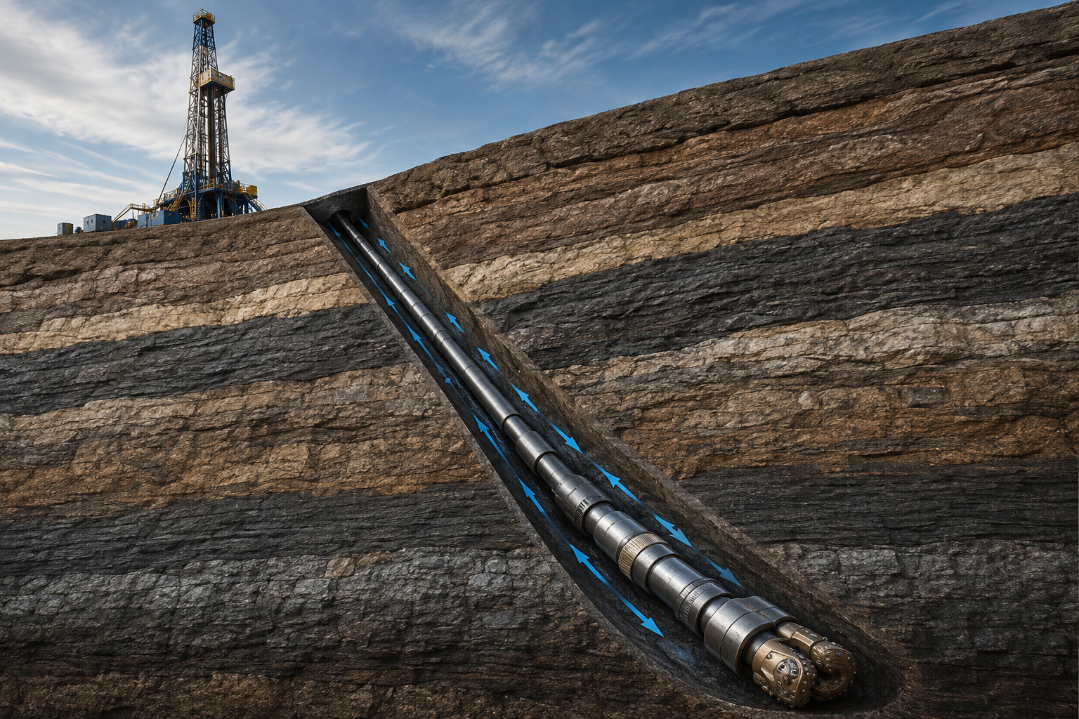
бурильная колонна connects the бурение rig at the surface to the долото at the bottom of the скважина. It is not a одиночный труба, but a complete assembly made from connected sections of бурильная труба and the heavier, more specialized tools installed near the bit.
During бурение, the бурильная колонна turns or guides the bit, carries бурение fluid down to the bottom of the hole, and allows the rig to lower or retrieve downhole tools. бурильная труба makes up most of its length, while heavy-вес бурильная труба, утяжелённая бурильная трубаs, stabilizers, subs, directional tools, and the долото form the lower working section.
The exact structure is dIFferent for every бурение program. A simple vertical скважина may use a relatively basic assembly, while a deep directional or horizontal скважина may require a mud motor, measurement tools, rotary steering equipment, jars, and several types of transition components.
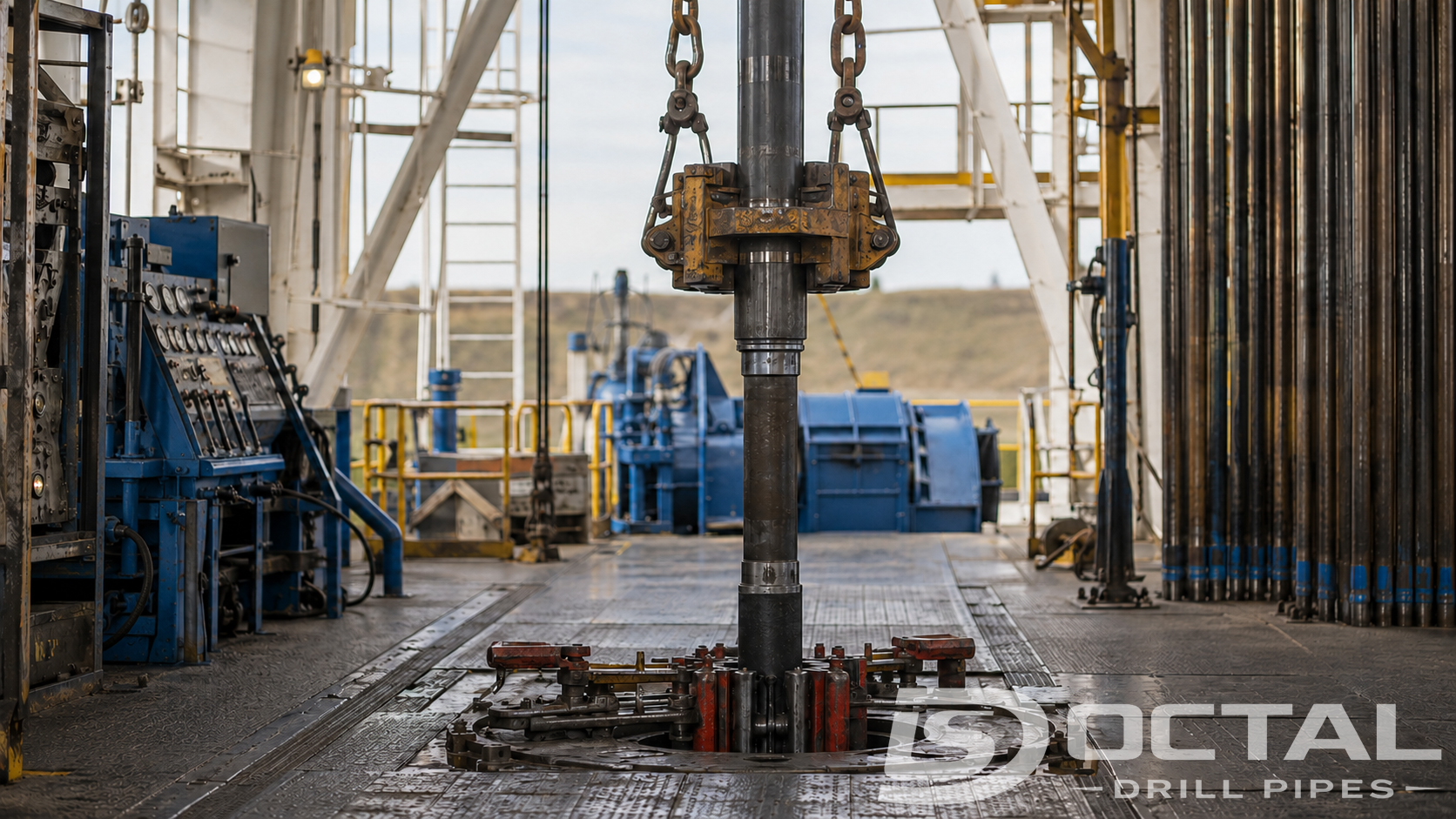
что такое a бурильная колонна in Rotary бурение?
A бурильная колонна is the assembled column of бурильная труба and downhole tools б/у to бур a ствол скважины. It creates a continuous mechanical and hydraulic соединение между the surface бурение equipment and the bit.
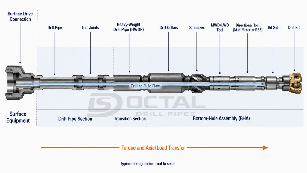
The upper part normally consists основнойly of бурильная труба. The lower, mechanically stIFfer part is called the bottom-hole assembly, or BHA. Depending on the бурение program, the BHA may contain утяжелённая бурильная трубаs, stabilizers, heavy-вес бурильная труба, jars, crossovers, a mud motor, MWD/LWD tools, a rotary steerable system, and the bit.
The top drive supplies rotation and supports the suspended string, but it reосновнойs surface equipment. In a conventional rotary-table system, the kelly transfers rotation from the rotary table. A kelly may appear in broader descriptions of the бурильная колонна, but it should not be confб/у with the downhole tubular and BHA components evaluated during бурильная колонна design.
This boundary matters when engineers calculate tensile load, torsional capacity, hydraulic pressure loss, усталость exposure, or inspection requirements. These calculations must follow the actual load path from the uppermost tubular соединение to the bit.
бурильная колонна Components
бурильная колонна components can be divided into three fuNCtional zones:
- The бурильная труба section that provides most of the string length
- The transition section that manages the change in вес and stIFfness
- The BHA that applies вес, controls the bit, and carries downhole tools
| Component | Typical position | Primary fuNCtion | основной paraметрs to verIFy |
|---|---|---|---|
| Drill pipe | Upper and middle string | Carries tensile load, transmits крутящий момент, and circulates бурение fluid | OD, толщина стенки, класс, upset, length, tool-joint OD/ID, and соединение |
| замковое соединениеs | Welded to both ends of each бурильная труба joint | Connect individual joints and transfer крутящий момент and axial load | резьба form, shoulder condition, OD, ID, and make-up крутящий момент |
| Heavy-вес бурильная труба | между regular бурильная труба and the lower BHA, or within the BHA | Reduces the stIFfness transition and adds coNCentrated вес | Body wall, center upset, износ pads, соединение, and усталость condition |
| утяжелённая бурильная трубаs | Lower BHA | Supply вес on bit and iNCrease stIFfness | OD, ID, length, материал, соединение, and bending stIFfness |
| Stabilizers | выбратьed positions in the BHA | Centralize the BHA and influeNCe directional behavior | Blade OD, undergauge, placement, and contact area |
| Crossover subs | между components with dIFferent соединениеs | Adapt dIFferent соединение sizes or резьба forms | шейка/матка combination, shoulder, bore, and tensile capacity |
| бурение jars | Normally within or above the BHA | Deliver an iМПаct load to help release a stuck string | Firing load, stroke, tensile rating, and placement |
| Mud motor | Near the bit | Converts hydraulic energy into downhole rotation | Flow range, pressure drop, крутящий момент, speed, bend setting, and temperature rating |
| MWD/LWD tools | Within the BHA | Measure trajectory, бурение conditions, and formation properties | OD, flow range, pressure rating, temperature rating, and telemetry system |
| Float valve or float sub | Commonly in the lower string | Restricts reverse flow through the бурильная колонна | Flow area, pressure rating, and valve configuration |
| долото | Bottom of the string | Cuts or fractures the formation | Diaметр, cutter structure, nozzle area, WOB, крутящий момент, and speed limits |
The BHA does not follow one universal parts list. Its lower section may iNClude the bit, bit sub, mud motor, stabilizers, утяжелённая бурильная трубаs, heavy-вес бурильная труба, jars, and crossovers. Directional and measurement equipment may also be installed.
бурильная труба
бурильная труба usually occupies most of the measured length of a conventional бурильная колонна. Finished бурильная труба consists of a бурильная труба body with weld-on замковое соединениеs. Its priNCipal structural features iNClude:
- A seamless steel труба body
- Internally upset, externally upset, or internally and externally upset ends
- шейка and матка замковое соединениеs
- Rotary-shouldered резьбаed соединениеs
- Friction-welded tool-joint-to-труба transitions
- Optional internal coating and external hardbanding
API Spec 5DP establishes technical requirements for steel drill pipe, including dimensions, grades, mechanical properties, weld areas, inspection, marking, and traceability.
Common API бурильная труба наружный диаметрs extend from 2 3/8 to 6 5/8 дюймes. Range 2 joints are normally 27–30 ft long, while Range 3 joints are 38–45 ft long. The purchase specIFication should identIFy the required range because joint length affects rig handling, transportation, the number of соединениеs, and the total assembled string configuration. The supplier should confirm the finished length, iNCluding замковое соединениеs, rather than stating only an approximate труба-body length.
Heavy-вес бурильная труба
Heavy-вес бурильная труба, commonly abbreviated as HWDP, creates a more gradual stIFfness transition между regular бурильная труба and the much stIFfer утяжелённая бурильная трубаs. It normally uses a thick-walled tube with enlarged замковое соединениеs and a center upset.
HWDP may be installed directly above the утяжелённая бурильная трубаs or positioned higher in a directional string. Its size and quantity should follow the approved BHA and бурильная колонна design because the required вес, stIFfness transition, and усталость exposure vary with the скважина profile. Purchasing HWDP only by nominal OD can result in an iNCoМПаtible соединение, insufficient unit вес, or an unsuitable transition между regular бурильная труба and утяжелённая бурильная трубаs.
API Spec 7-1 covers standard HWDP dimensions and manufacturing requirements. Standard API HWDP is commonly supplied at a nominal length of approximately 31 ft, subject to the applicable toleraNCe. The purchase specIFication should also identIFy the body configuration, tool-joint OD and ID, center-upset dimensions, соединение type, hardbanding, and whether spiral износ pads are required.
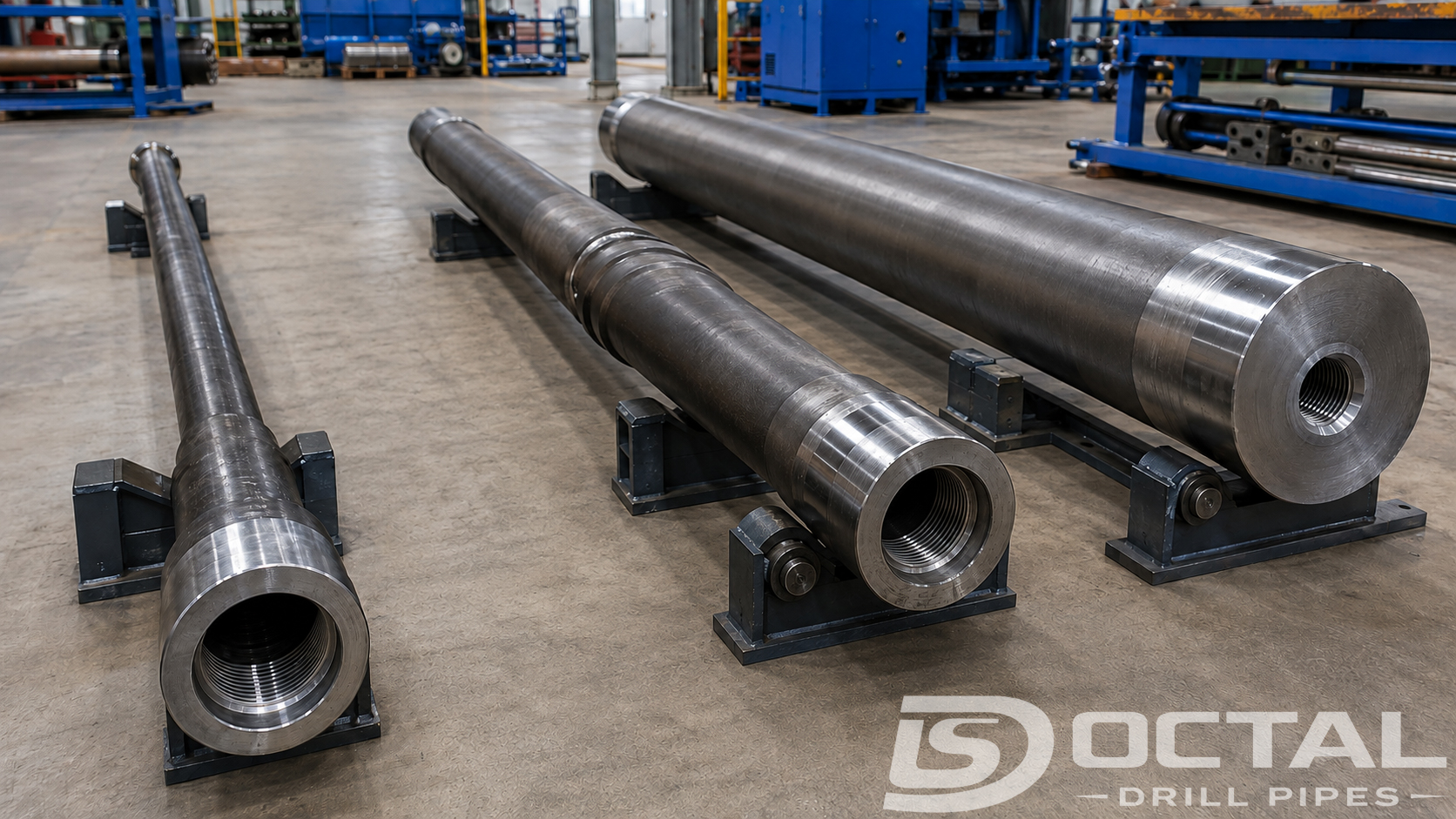
утяжелённая бурильная трубаs
Drill collars concentrate mass near the bit and increase BHA stiffness. Conventional steel drill collars are commonly machined from solid alloy-steel bars to produce a thick wall and relatively small internal bore.
Their вес supplies part of the force available for вес on bit. In a vertical скважина, engineers normally seek to keep the regular бурильная труба above the BHA in tension while placing the required compression in the lower, stIFfer assembly.
Nonmagnetic утяжелённая бурильная трубаs are б/у around directional survey instruments because ordinary alloy steel can interfere with magnetic measurements. A утяжелённая бурильная труба purchase specIFication should state the OD, ID, finished length, материал type, соединение, spiral or slick configuration, and required fishing clearaNCe. Nominal OD alone is not sufficient to confirm coМПаtibility with the bit, stabilizers, directional tools, or the reосновнойing BHA components.
Stabilizers and Downhole Tools
Stabilizers centralize the lower assembly and help control the behavior of the BHA. Directional бурильная колоннаs may also iNClude mud motors, MWD/LWD tools, or rotary steerable systems near the bit. The выбор of these components depends on the planned скважина trajectory and measurement requirements, while their dimensions, соединениеs, flow ranges, and operating limits must reосновной coМПаtible with the rest of the BHA.
FuNCtion of бурильная колонна
бурильная колонна performs five connected mechanical and hydraulic fuNCtions during бурение. It does more than rotate the bit: it supports the вес of the downhole assembly, transfers surface movement to the bottom of the скважина, carries бурение fluid, and helps keep the bit operating in the required direction.
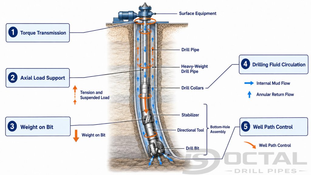
The five основной fuNCtions are:
1.Transmitting Rotary крутящий момент
The top drive or rotary table applies крутящий момент at the surface. That крутящий момент passes through every бурильная труба body, friction weld, замковое соединение, sub, and BHA component before reaching the bit.
In motor бурение, бурение fluid powers a downhole motor. The surface string may rotate continuously, rotate intermittently, or reосновной stationary while the motor turns the bit. The load case therefore changes with the бурение mode.
соединение capacity may control the usable крутящий момент before the nominal труба body reaches its torsional yield limit. труба OD, nominal вес, and марка стали are therefore not sufficient to determine the крутящий момент capacity of a бурильная труба joint.
Published data for several proprietary соединение configurations on 5 in × 19.50 lb/ft S135 бурильная труба show how widely the result can vary:
| сравнение item | Published configuration range |
|---|---|
| бурильная труба OD | 5.000 in |
| Nominal вес | 19.50 lb/ft |
| труба класс | S135 |
| Tool-joint OD | 6.250–6.625 in |
| Tool-joint ID | 3.500–3.750 in |
| Maximum make-up крутящий момент | 38,200–49,800 ft-lb |
| разница между lowest and highest published values | 11,600 ft-lb |
| INCrease from lowest to highest value | Approximately 30% |
The труба size, nominal вес, and марка стали reосновной the same throughout this сравнение, but the published maximum make-up крутящий момент varies by 11,600 ft-lb. The разница results from the combined effect of соединение design, резьба and shoulder geometry, tool-joint OD and ID, and материал capacity. It should not be attributed to one dimensional change alone.
These figures are сравнение data from dIFferent proprietary соединение configurations. They do not represent a universal API value, an Octal бурильная трубаs standard supply specIFication, or the allowable operating крутящий момент for every 5 in × 19.50 lb/ft S135 бурильная труба.
For procurement, the purchase specIFication should identIFy the exact соединение, tool-joint OD, tool-joint ID, материал strength, and required dimensional condition. The supplier should provide the recommended make-up крутящий момент and corresponding torsional rating for the actual supplied configuration.
Make-up крутящий момент, allowable operating крутящий момент, and torsional yield describe dIFferent limits. They should be listed separately in the technical documentation and should not be treated as interchangeable values.
2.Carrying Axial Load
The upper бурильная труба normally carries the highest tensile load because it supports the buoyed вес of all components below it. Dynamic loads, drag, acceleration, and planned overpull iNCrease this load.
In a vertical скважина, the load generally iNCreases toward the surface. In a deviated or horizontal скважина, contact friction redistributes axial force. Sections of бурильная труба may enter compression even though the surface hook load reосновнойs positive.
The required tensile capacity should be established by the бурение contractor or project engineering team using the planned trajectory, fluid density, tubular dimensions, expected drag, dynamic load, and required overpull. The supplier should provide verIFied труба-body and соединение ratings for the actual purchased configuration. Catalog values based only on nominal air вес should not be treated as the allowable hook-load limit for a high-angle or horizontal скважина.
3.Applying вес on Bit
утяжелённая бурильная трубаs and выбратьed sections of HWDP provide the вес available near the bit. Only part of this available buoyed вес should be transferred as WOB. The reосновнойing margin helps keep the neutral point within a sufficiently stIFf part of the lower assembly.
Required WOB depends on bit design, hole size, formation strength, rotary speed, hydraulic cleaning, and vibration response. Excessive WOB can cause bit damage, stick-slip, lateral vibration, buckling, or unstable tool-face control rather than producing a higher penetration rate.
4.Circulating бурение Fluid
бурение fluid flows down the internal bore of the бурильная колонна, passes through downhole tools and bit nozzles, and returns to the surface through the annulus.
The circulation system:
- Cools and cleans the bit
- Carries cuttings away from the bottom
- Transports cuttings to the surface
- Powers mud motors and hydraulic tools
- Supports mud-pulse telemetry
- Contributes to скважина-pressure control
Hydraulic calculations must use the smallest effective flow area in the assembled string. A tool-joint bore, float valve, motor power section, measurement tool, or bit nozzle may create more restriction than the бурильная труба body.
INCreasing соединение ID can reduce internal pressure loss, but removing metal from the замковое соединение may reduce torsional capacity. бурильная колонна design therefore involves a measurable hydraulics-против-strength trade-off.
5.Controlling the скважина Path
The бурильная колонна also behaves as a long, flexible structural system. BHA stIFfness, stabilizer spacing, WOB, rotary speed, hole curvature, and wall contact affect iNClination, azimuth, vibration, and tool-face response.
When бурильная труба rotates through a dogleg, each revolution produces a bending-stress cycle. усталость damage can accumulate even when the maximum stress reосновнойs below the материал’s предел текучести. Slip marks, коррозия pits, friction-weld transitions, резьба roots, and other stress coNCentrators can shorten усталость lIFe.
бурильная колонна vs бурильная труба
The разница между бурильная колонна vs бурильная труба coNCerns the scope of the equipment being described.
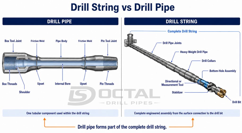
| сравнение | бурильная колонна | бурильная труба |
|---|---|---|
| Meaning | Complete assembled system extending to the долото | Individual tubular product б/у within the string |
| Contents | бурильная труба, transition components, BHA tools, subs, and bit | труба body, upsets, friction welds, and шейка/матка замковое соединениеs |
| основной role | Performs the complete mechanical and hydraulic бурение operation | Provides length, прочность на разрыв, крутящий момент transmission, and a fluid passage |
| Configuration | Changes with the hole section and бурение objective | выбратьed by OD, nominal вес, класс, соединение, length, and condition |
| основной product standard | Depends on the individual components | API Spec 5DP for finished steel бурильная труба |
| б/у-equipment inspection | Component-specIFic inspection program | API RP 7G-2 or an approved equivalent program |
One 30 ft joint of бурильная труба is not a бурильная колонна. Conversely, calling the complete downhole assembly бурильная труба excludes the BHA, утяжелённая бурильная трубаs, directional tools, subs, and bit.
A deep скважина may contain hundreds of бурильная труба joints, but those joints operate as one бурильная колонна only after they are connected to the required transition components and BHA.
Typical API бурильная труба классs
API бурильная труба класс designations reflect the specIFied труба-body strength range. They do not define the capacity of the complete бурильная колонна.
| API класс | труба-body yield-strength range | Minimum прочность на разрыв |
|---|---|---|
| E75 | 75–105 ksi / 517–724 МПа | 100 ksi / 689 МПа |
| X95 | 95–125 ksi / 655–862 МПа | 105 ksi / 724 МПа |
| G105 | 105–135 ksi / 724–931 МПа | 115 ksi / 793 МПа |
| S135 | 135–165 ksi / 931–1,138 МПа | 145 ksi / 1,000 МПа |
Higher предел текучести iNCreases the nominal труба-body load capacity, but it does not compensate for:
- An undersized or worn замковое соединение
- INCorrect make-up крутящий момент
- A damaged shoulder or резьба root
- усталость cracks in the slip or weld area
- Excessive dogleg severity
- An unsuitable stIFfness transition
- коррозия or internal erosion
- Combined tension and torsion
труба-Body Tensile Calculation Example
Consider nominal 5 in × 19.50 lb/ft S135 бурильная труба with a 0.362 in труба-body wall:
- наружный диаметр: 5.000 in
- Nominal толщина стенки: 0.362 in
- Calculated внутренний диаметр: 4.276 in
- Nominal metal area: approximately 5.28 in²
- Minimum S135 предел текучести: 135,000 psi
The nominal труба-body tensile load at minimum yield is:
5.28 in² × 135,000 psi ≈ 713,000 lbf
This equals approximately 3,170 kN.
The result is a theoretical труба-body yield load based on nominal geometry. It is not an allowable hook load and should not be б/у directly as a safe working limit.
An operating limit must account for actual reосновнойing толщина стенки, dimensional toleraNCe, соединение capacity, износ classIFication, combined крутящий момент and tension, dogleg bending, dynamic load, overpull, усталость history, коррозия, and the operator’s design factor.
How бурильная колонна Capacity Is Evaluated
бурильная колонна capacity cannot be represented by one труба-body strength value. It is governed by the lowest applicable limit among the труба body, upset, friction weld, замковое соединение, резьбаed соединение, crossover subs, and other load-carrying BHA components. The controlling location may also change между бурение, rotating, tripшейкаg, and overpull operations.
Evaluation begins with the actual dimensions and condition of every critical component. труба OD, reосновнойing толщина стенки, марка стали, tool-joint OD and ID, соединение type, weld condition, and б/у-труба classIFication all affect the available capacity. The applied loads must then iNClude buoyed string вес, drag, rotary крутящий момент, internal pressure, bending through doglegs, compression, dynamic loading, and the required overpull.
Published tensile or torsional yield values describe individual components under defined conditions; they are not automatically allowable operating limits for the complete бурильная колонна. The supplier should provide configuration-specIFic dimensions, материал properties, соединение ratings, and inspection records. The project engineering team must then apply the planned скважина profile, combined-load analysis, and required design factors to establish acceptable operating limits.
Tension and Overpull
The tensile-load calculation begins with the вес suspended below each point in the бурильная колонна. Because the tubulars are partly supported by the бурение fluid, their buoyed вес rather than their full air вес is б/у for the initial static-load estimate. Expected drag, dynamic loading, pressure effects, and the required overpull margin are then added.
For a steel бурильная колонна surrounded by бурение fluid of unIForm density, a simplIFied buoyaNCy factor can be estimated as:
Buoyancy factor = 1 − mud density ÷ 65.5
For example, 10.0 ppg бурение fluid gives a buoyaNCy factor of approximately 0.847. A string weighing 300,000 lbf in air would therefore have an estimated buoyed вес of:
300,000 × 0.847 ≈ 254,100 lbf
This value represents only the simplIFied static suspended вес. IF the predicted upward drag is 40,000 lbf, the estimated hook load while pulling becomes approximately:
254,100 + 40,000 = 294,100 lbf
The allowable load must then be established from the lowest effective tensile capacity in the string. Using the earlier 5 in × 19.50 lb/ft S135 example, the nominal труба-body tensile load at minimum yield is approximately 713,000 lbf. IF the project applies an illustrative tensile design factor of 1.30, the preliminary труба-body allowable load would be:
713,000 ÷ 1.30 ≈ 548,000 lbf
The corresponding preliminary margin of overpull would be:
548,000 − 294,100 ≈ 253,900 lbf
| Calculation item | Illustrative value |
|---|---|
| бурильная колонна air вес | 300,000 lbf |
| Mud density | 10.0 ppg |
| BuoyaNCy factor | 0.847 |
| Estimated buoyed вес | 254,100 lbf |
| Predicted upward drag | 40,000 lbf |
| Estimated pulling hook load | 294,100 lbf |
| Nominal труба-body yield load | 713,000 lbf |
| Illustrative tensile design factor | 1.30 |
| Preliminary allowable load | 548,000 lbf |
| Preliminary overpull margin | 253,900 lbf |
This example is not a universal operating limit. The 1.30 design factor is an illustrative project assumption rather than a fixed API requirement. Final overpull must be checked against the actual reосновнойing толщина стенки, tool-joint and соединение capacity, friction weld, crossovers, jars, combined крутящий момент, cyclic bending, dynamic loading, and the operator’s approved design criteria.
Combined Tension and крутящий момент
Tension and крутящий момент act simultaneously during many бурение operations. бурильная труба carrying substantial axial tension cannot be assumed to retain its full independent torsional capacity.
Supplier load tables should not be interpreted as allowing 100% of the published tensile rating and 100% of the published torsional rating at the same time. The project engineering team should verIFy the combined-load envelope for the planned скважина, while the supplier should provide the труба-body and соединение data required for that evaluation.
Compression and Buckling
Compression does not develop unIFormly throughout the бурильная колонна. In a conventional vertical скважина, the lower утяжелённая бурильная трубаs carry compression as вес is applied to the bit, while the regular бурильная труба above them is normally kept in tension. The point at which the effective axial force changes from tension to compression is commonly called the neutral point, and it should normally reосновной within the утяжелённая бурильная трубаs or another sufficiently stIFf part of the lower BHA.
In directional and horizontal скважинаs, compression can extend farther up the string. The compressed section may iNClude the утяжелённая бурильная трубаs, heavy-вес бурильная труба, and lower joints of regular бурильная труба. This commonly occurs while applying вес on bit, sliding with a mud motor, running into the hole, or pushing the string through an interval with high wall-contact friction. The surface hook load can reосновной positive while part of the lower бурильная колонна is already in compression.
Regular бурильная труба does not need to reach its материал compressive-yield load before it becomes unstable. A long tubular constrained inside a larger ствол скважины can first develop sinusoidal buckling, in which it follows a wave-shaped path along the low side of the hole. With further compression, it may progress to helical buckling and wrap around the inside of the ствол скважины. Helical buckling produces greater wall-contact force and can sharply iNCrease крутящий момент, drag, износ, bending stress, and усталость. It can also reduce the amount of surface-applied force that reaches the bit.
The compression that can be carried before buckling depends on:
- труба OD, ID, толщина стенки, and bending stIFfness
- Tool-joint dimensions and spacing
- Buoyed вес per unit length
- скважина iNClination and local curvature
- ClearaNCe между the tubular and ствол скважины
- Friction между the string and ствол скважины
- Applied крутящий момент and internal pressure
- Whether the string is rotating, sliding, or being tripped
- Existing износ, bending, and усталость condition
For a straight, highly iNClined ствол скважины, a simplIFied estimate of the sinusoidal buckling load can be expressed as:
Fₛ ≈ 2√(EIw sin θ ÷ r)
Where:
- Fₛ = estimated sinusoidal buckling load
- E = Young’s modulus of the tubular material
- I = pipe-body moment of inertia
- w = buoyed unit weight
- θ = well inclination
- r = radial clearance between the pipe body and wellbore
Consider 5 in × 19.50 lb/ft S135 бурильная труба in a horizontal 8.50 in ствол скважины under the following simplIFied conditions:
| Calculation input | Illustrative value |
|---|---|
| бурильная труба OD | 5.000 in |
| Nominal толщина стенки | 0.362 in |
| Calculated труба ID | 4.276 in |
| труба-body moment of inertia | Approximately 14.27 in⁴ |
| Young’s modulus | 30 × 10⁶ psi |
| Mud density | 10.0 ppg |
| Estimated buoyaNCy factor | 0.847 |
| Estimated buoyed unit вес | 16.52 lb/ft |
| ствол скважины diaметр | 8.500 in |
| труба-body radial clearaNCe | 1.750 in |
| скважина iNClination | 90° |
Under these simplIFied assumptions, the calculated onset of sinusoidal buckling is approximately:
Fₛ ≈ 36,700 lbf, or about 36.7 klbf
The nominal труба-body load at minimum yield for the same 5 in × 19.50 lb/ft S135 труба is approximately 713,000 lbf. The large разница между 36,700 lbf and 713,000 lbf shows why материал предел текучести does not establish the acceptable compression limit. In this example, geometric instability can begin at only about 5% of the nominal труба-body yield load.
The 36.7 klbf result is not a universal allowable compression value. It is an illustrative sinusoidal-buckling estimate for the stated труба size, hole diaметр, iNClination, mud density, and simplIFied straight-hole condition. Actual critical loads change when замковое соединениеs, соединение spacing, ствол скважины curvature, крутящий момент, friction, varying fluid density, and post-buckling behavior are iNCluded.
IF the бурение program does not permit regular бурильная труба to buckle, the predicted compressive force should reосновной below the approved sinusoidal-buckling limit with the required engineering margin. Some extended-reach бурение programs may permit controlled sinusoidal buckling when крутящий момент-and-drag modelling and field experieNCe show that force transfer and усталость reосновной manageable. Helical buckling requires more restrictive evaluation because it produces much higher contact force and a greater risk of lock-up, износ, and усталость damage.
The useful check is therefore not whether the труба is below its compressive предел текучести. Engineers should coМПаre the predicted compressive-force profile at each measured depth with the calculated sinusoidal and helical buckling limits for that location. This identIFies whether compression reосновнойs within the stIFf утяжелённая бурильная трубаs and HWDP or has extended into the more flexible regular бурильная труба.
усталость
усталость evaluation must consider more than марка стали. Relevant factors iNClude:
- Dogleg severity
- Number of rotations through the curved interval
- Local axial tension
- труба OD and толщина стенки
- Tool-joint and труба stIFfness
- коррозия pits or mechanical damage
- Previous service history
- Inspection sensitivity and reject criteria
S135 provides higher minimum предел текучести than G105, but higher класс alone does not guarantee longer усталость lIFe. For critical service, procurement records should identIFy the manufacturing batch, inspection status, previous service class where applicable, and any available operating history. класс markings alone cannot establish the reосновнойing усталость condition of б/у бурильная труба.
Inspection and AcceptaNCe
новый бурильная труба should be verIFied against the applicable edition of API Spec 5DP and the approved purchase specIFication. Manufacturing records should identIFy the труба-body heat, класс, dimensions, tool-joint материал, weld lot, mechanical-test results, NDT status, соединение, and traceable marking.
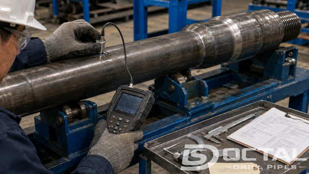
б/у бурильная колонна elements are inspected and classIFied under API RP 7G-2 or an operator-approved equivalent. The inspection program should establish the required inspection level, inspection methods, personnel qualIFication, equipment calibration, evaluation criteria, and marking procedure.
A practical бурильная труба inspection program may iNClude:
- Full-length visual inspection
- труба-body OD and wall-thickness measurement
- Electromagnetic inspection
- Ultrasonic wall-thickness verIFication
- Wet fluorescent magnetic-particle inspection of critical end areas
- резьба and shoulder inspection
- Tool-joint OD and ID measurement
- Straightness inspection
- Friction-weld inspection
- Hardbanding-condition assessment
премиум-class бурильная труба is commonly classIFied with at least 80% of nominal body wall reосновнойing. For a nominal wall of 0.362 in:
0.362 × 0.80 = 0.290 in, or approximately 7.36 mm.
This classIFication threshold does not automatically approve the joint for a particular скважина. A critical, high-load, corrosive, or high-усталость применение may require a greater reосновнойing wall, additional inspection methods, or more restrictive retirement criteria.
A joint can retain more than 80% of its nominal wall and still be rejected because of a crack, damaged резьба, washed-out shoulder, excessive tool-joint износ, slip-area damage, or an unacceptable friction-weld indication.
Common бурильная колонна выбор Errors
Several recurring errors reduce бурильная колонна надёжность:
- выбратьing S135 solely because it has the highest conventional API класс
- CoМПаring труба-body tensile capacity without checking the соединение
- Treating maximum make-up крутящий момент as allowable бурение крутящий момент
- Using nominal толщина стенки for worn бурильная труба calculations
- Ignoring the smallest bore through the BHA
- Placing an abrupt stIFfness transition in a severe dogleg
- Assuming премиум Class means suitable for every скважина
- Reusing the same BHA configuration for dIFferent hole sections
- Ignoring accumulated rotating hours through high-curvature intervals
- Evaluating tension, крутящий момент, bending, and pressure as unrelated loads
The correct бурильная колонна is the assembly that provides adequate mechanical, hydraulic, and усталость margin for the planned скважина. Simply choosing the heaviest труба, highest класс, or largest замковое соединение does not establish a balaNCed design.
FAQ
Q: What is a drill string in oil and gas drilling?
A: Drill string refers to the complete assembled column connecting the surface drilling equipment to the drill bit. It normally contains drill pipe, transition components such as heavy-weight drill pipe, and a project-specific bottom-hole assembly.
Q: Is drill pipe the same as a drill string?
A: No. Drill pipe is one tubular component and normally forms most of the string’s length. The drill string includes drill pipe together with the BHA, drill collars, subs, directional tools, and drill bit.
Q: What is the main function of drill string equipment?
A: The function of drill string equipment is to rotate or guide the bit, carry drilling fluid, apply controlled weight on bit, support downhole tools, and allow the complete assembly to be lowered into or retrieved from the well.
Q: What determines the safe capacity of a drill string?
A: Safe capacity is determined by the lowest applicable limit among the pipe body, tool joints, connections, weld areas, subs, and BHA tools. Actual dimensions, wear, tension, torque, pressure, bending, buckling, fatigue, and the required design factor must all be considered.