
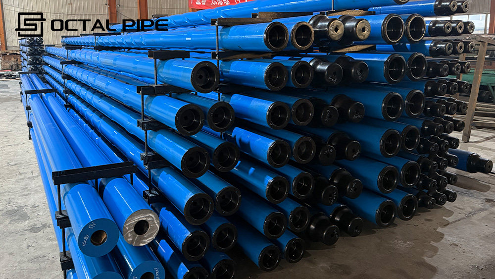
What is drill pipe?
Drill pipe is the main tubular component used to transmit rotary torque, circulate drilling fluid, and connect the surface system with the bottom hole assembly during drilling operations. In actual service, drill pipe works under combined loads rather than a single load case. Internal pressure, external pressure, torque, bending, tension, vibration, and repeated make-and-break all affect service life and connection reliability.API 5DP drill pipe is the common reference used for grade, size, upset type, connection, and length classification in commercial supply. That is why drill pipe selection is not based on OD and grade alone. Buyers also need to evaluate upset type, thread connection, length range, weld quality, inspection scope, and field suitability.
As a new product line introduced by Octal Steel, this platform is dedicated to drill pipe, heavy weight drill pipe, and related drilling products for onshore and offshore operations.OCTAL DRILL PIPE manufacturers supplies API 5DP drill pipe in common grades, sizes, and thread connections for onshore and offshore drilling applications. This page brings together the main specification points buyers usually need to review, including grades, sizes, thread types, heavy weight drill pipe, inspection methods, and common service considerations.
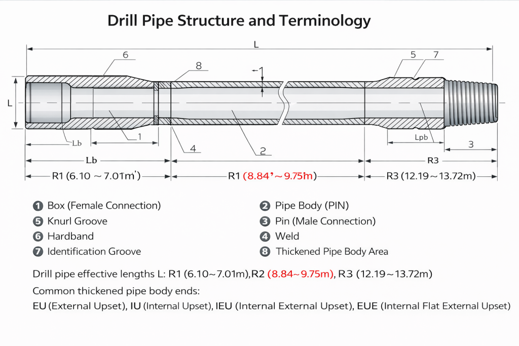
Drill Pipe Sizes and Common Configurations
Drill pipe sizes are one of the most searched drill pipe topics because OD, wall thickness, and tool joint combination directly affect hydraulic performance, string weight, torque capacity, and connection selection.
Below are common drill pipe size and configuration examples used in API 5DP supply:
This is why a “drill pipe” inquiry is usually incomplete if it includes only OD. In most cases, buyers should also define grade, upset type, connection, range, and intended service condition.
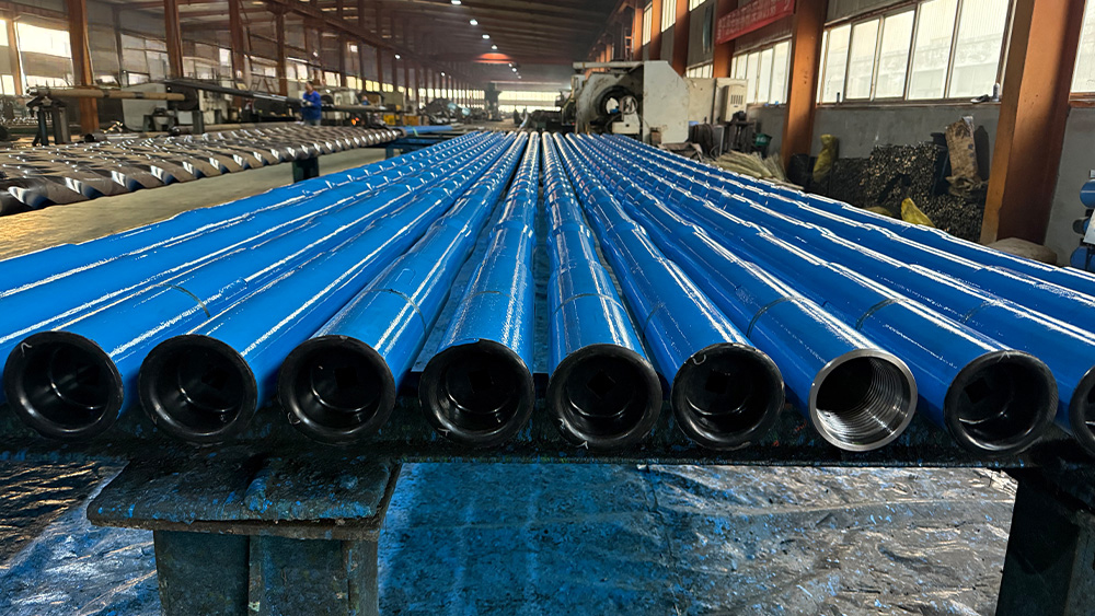
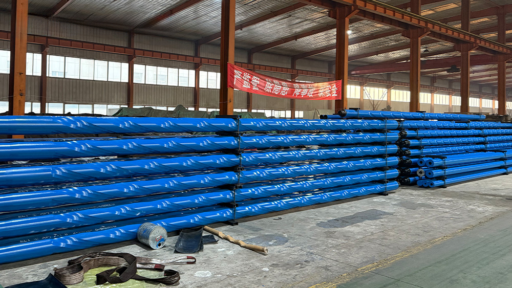
API 5DP Drill Pipe Grades
| Item | Common Options |
|---|---|
| Grade | E75, X95, G105, S135, V150 |
| OD | 2 3/8″, 2 7/8″, 3 1/2″, 4″, 4 1/2″, 5″, 5 1/2″, 6 5/8″ |
| OD in mm | 60.3, 73.0, 88.9, 101.6, 114.3, 127.0, 139.7, 168.3 |
| Connection | NC26, NC31, NC38, NC40, NC46, NC50, 5 1/2 FH, 6 5/8 FH |
| Upset Type | IU, EU, IEU |
| Length Range | R1, R2, R3 |
In procurement, grade selection should always be reviewed together with drilling depth, well profile, torque demand, connection type, fatigue exposure, and overall cost target. A higher grade is not automatically the better choice if the real operating condition is controlled by connection capacity, service life, or budget. In practice, buyers usually evaluate drill pipe grade together with the expected drilling load and the full string design rather than treating grade as a standalone specification.
Drill Pipe Stress, Deflection, and Fatigue Life
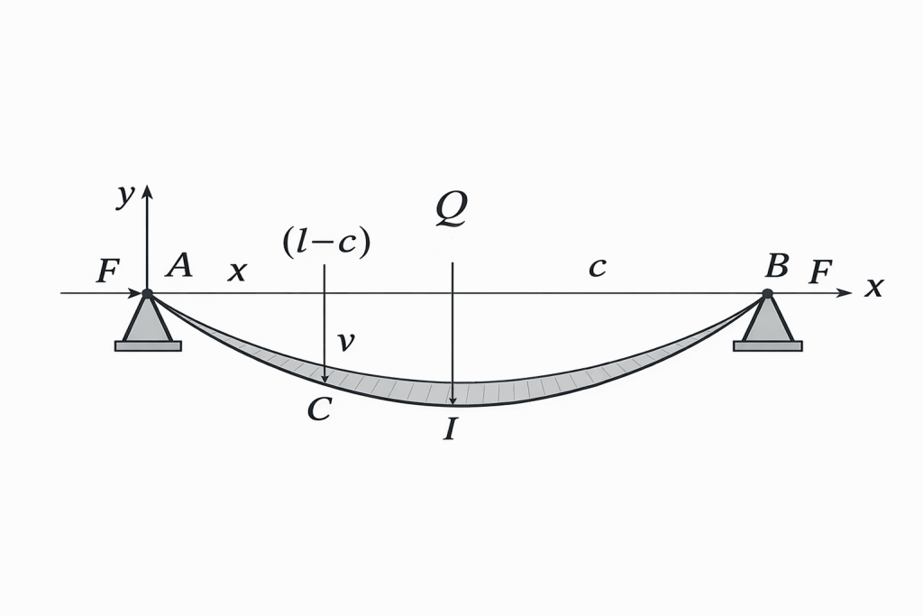
The first diagram illustrates a simplified stress and deflection model of drill pipe under load. With axial force F acting at both ends, the pipe still develops downward bending deformation, and the vertical displacement v increases toward the middle span, where the lowest point Q appears. This helps explain why drill pipe in service is affected by combined loading rather than straight axial force alone. Once bending is introduced, stress concentration becomes more severe in fatigue-sensitive areas such as the upset transition, weld zone, and threaded connection.
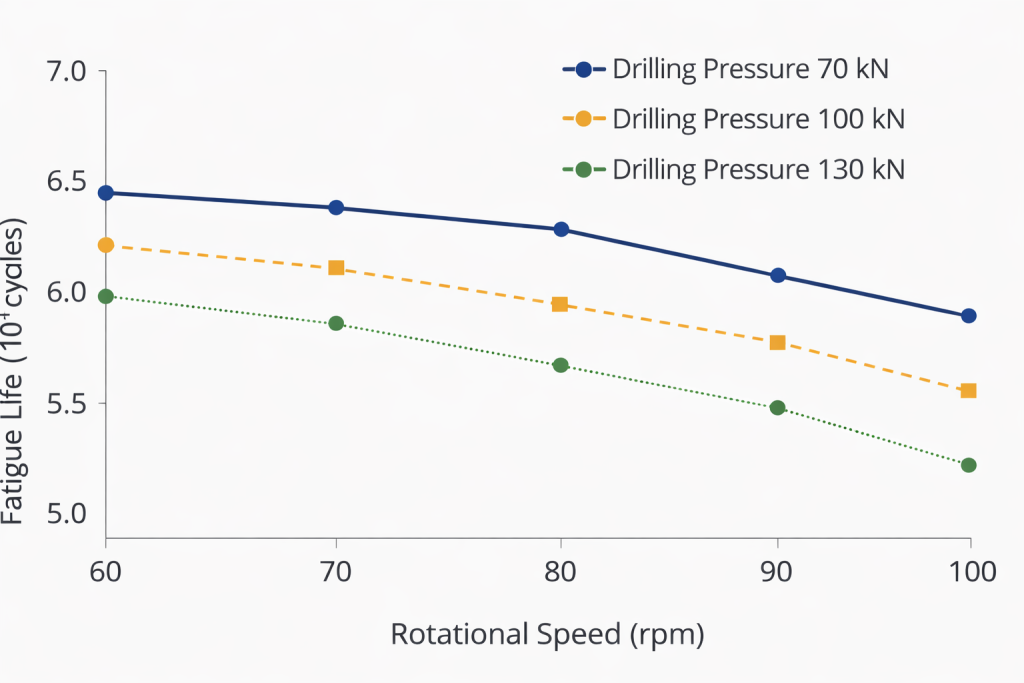
The second diagram shows the effect of rotational speed and drilling pressure on fatigue life. The fatigue life decreases as speed increases from 60 to 100 rpm, and it also decreases as drilling pressure rises from 70 kN to 130 kN. In other words, higher speed and higher load both shorten drill pipe life by accelerating cyclic stress damage. This is why drill pipe selection should consider not only size and grade, but also operating profile, connection design, and fatigue-related inspection requirements.
Drill Pipe Threads and Connections
Drill pipe threads are one of the most critical selection points because the connection area carries the highest combination of torque, bending, shoulder contact stress, and repeated make-and-break loading in the drill string. In field service, many serious drill pipe failures start at the connection rather than in the plain body, including thread galling, shoulder damage, fatigue cracking near the last engaged thread, connection loosening, washout, and even twist-off under high torque.
Common rotary shouldered drill pipe connections include:
- NC26
- NC31
- NC38
- NC40
- NC46
- NC50
- NC52
- 5 1/2 FH
- 6 5/8 FH
The connection choice affects more than interchangeability. It defines the usable torque envelope, shoulder contact stability, make-up behavior, and compatibility with the existing drill string and bottom hole assembly. In practical selection, a request for NC50 drill pipe is not just a request for a thread name. It usually means the buyer is defining a higher connection capacity and a specific tool joint class for the string. Smaller drill pipe sizes may use NC31, NC38, or NC40, while larger or heavier string sections may require NC46, NC50, or FH connections to handle higher torque and stronger transition demand.
| Connection | Typical consideration |
|---|---|
| NC31 / NC38 | Smaller drill pipe sizes and moderate torque demand |
| NC40 / NC46 | Standard drilling strings with higher load requirement |
| NC50 / NC52 | Higher torque capacity and larger drill string applications |
| 5 1/2 FH / 6 5/8 FH | Heavy-duty string sections with stronger shoulder area |
How API 5DP Drill Pipe Is Manufactured?
Reliable API drill pipe depends on more than steel grade alone. In actual manufacturing, the pipe body is typically produced from seamless tube, while the box and pin tool joints are made separately from alloy steel. The pipe ends are upset to reinforce the connection zone, the tool joints are machined and heat treated, and both parts are then joined by friction welding. After welding, the drill pipe goes through precision machining, thread finishing, dimensional inspection, straightness control, and non-destructive testing before release.
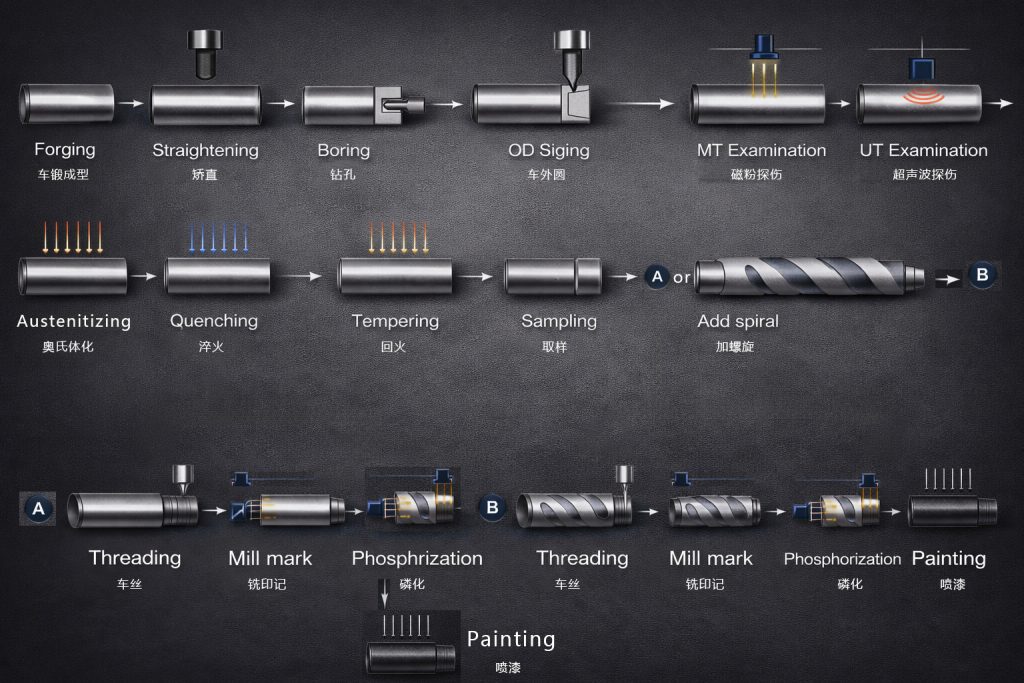
For buyers, the most important quality control areas usually include:
- tool joint machining accuracy
- upset quality
- friction weld integrity
- heat treatment consistency
- thread profile accuracy
- hardness control
- dimensional stability
- product traceability
This is also where a serious drill pipe manufacturer can distinguish product quality beyond basic specification matching.
How Drill Pipe Works?
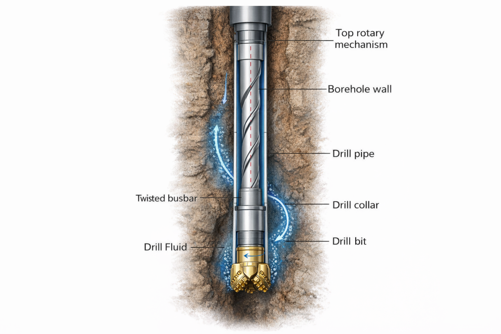
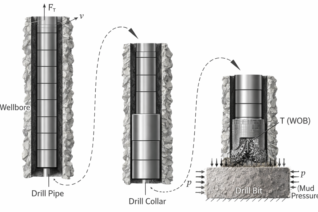
Drill pipe is the main tubular component that connects the surface rotary system to the bottom hole assembly and drill bit. In drilling operations, it performs three core functions at the same time: transmitting rotary torque to the bit, carrying axial load such as string weight and weight on bit (WOB), and circulating drilling fluid through the inside of the pipe to the bottom of the hole.
As the string rotates, torque is transferred from the top drive or rotary table through the tool joints and pipe body to the drill bit. At the same time, drilling fluid is pumped down the inside of the drill pipe, exits through the bit nozzles, cools and cleans the bit, and then carries cuttings back to surface through the annulus between the pipe and borehole wall. This continuous cycle allows the drill string to cut formation, remove debris, and maintain stable drilling progress.
In a typical drill string, drill pipe works together with drill collars, stabilizers, and the drill bit. The drill collars provide concentrated weight near the bottom, while the drill pipe mainly provides reach, rotation, and fluid transmission along the well path. Because the pipe is exposed to tension, torsion, bending, and cyclic fatigue during drilling, grade selection, connection type, wall thickness, and inspection condition all directly affect service life and drilling reliability.
Heavy Weight Drill Pipe
What is Heavy Weight Drill Pipe?
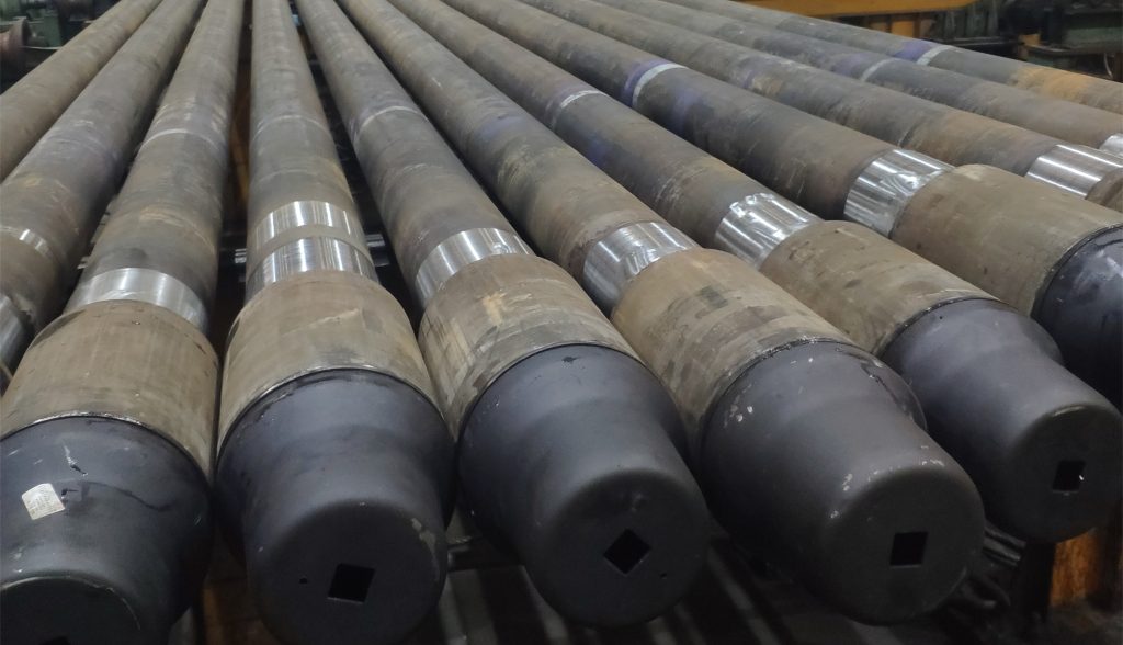
Heavy Weight Drill Pipe (HWDP) is a transition member used between standard drill pipe and drill collars in the drill string. Its main job is to make the change in stiffness and section less abrupt, so load transfer is smoother and stress concentration at the connection area is reduced. This helps improve drill string stability and lowers fatigue risk, especially in directional, deviated, and deeper wells.
In practical drilling programs, standard drill pipe is often discussed by grades such as E75, X95, G105, and S135, while HWDP is usually selected as the heavy transition section between those drill pipe grades and the heavier bottom-hole assembly. Many HWDP products are commonly manufactured from high-strength alloy steel such as 4145H modified material, because the priority is not only strength level, but also better torsional performance, wear resistance, and transition reliability in the string.
Heavy Weight Drill Pipe Specifications, Types and Sizes
Drill Pipe vs Heavy Weight Drill Pipe Advantages and How to Choose
Standard drill pipe and heavy weight drill pipe do not serve the same role in the drill string. Standard drill pipe is the main section used to transmit torque, carry tensile load, and circulate drilling fluid through most of the well interval. Heavy weight drill pipe is used as a transition member between drill pipe and drill collars, where a smoother stiffness change is needed to improve load transfer and reduce fatigue concentration. In practical drilling design, the question is usually not which one is better, but how to combine them correctly for the well profile and drilling objective.
| Comparison Item | Drill Pipe | Heavy Weight Drill Pipe |
|---|---|---|
| Primary role | Main drill string member for transmitting torque, carrying tensile load, and circulating drilling fluid through the main well interval. | Transition member placed between drill pipe and drill collars to improve stiffness transition and load distribution. |
| Main advantage | Lower string weight over long intervals, broad grade coverage, and reliable performance for most standard drilling sections. | Better weight transfer, improved transition strength, reduced stress concentration, and lower fatigue exposure near the BHA transition zone. |
| Common grade or material reference | Usually specified by grades such as E75, X95, G105, and S135, depending on depth, torque, and tensile requirement. | Commonly manufactured from high-strength alloy steel such as 4145H modified material, with more focus on transition performance, wear resistance, and fatigue control. |
| Typical use position | Used through the main length of the drill string. | Used above drill collars and below the standard drill pipe section. |
| Best suited drilling conditions | Vertical wells, general drilling intervals, and long sections where the main requirement is reliable torque and tensile transmission. | Directional wells, high-angle wells, deeper wells, and drilling programs where the stiffness jump between drill pipe and drill collars needs to be reduced. |
| Why buyers specify it | To match hole size, grade requirement, connection type, tensile capacity, and expected operating torque for the main drill string. | To stabilize the lower string section, improve drilling behavior, and reduce fatigue-related risk in the transition area. |
FAQ
Q1. Which drill pipe grade should I choose: E75, X95, G105, or S135?
A1. E75, X95, G105, and S135 are the most common commercial API 5DP drill pipe grades. In general, E75 is used for lighter service, X95 and G105 are widely used for standard drilling programs, and S135 is preferred for deeper wells and higher load conditions.
Q2. What are the most common drill pipe sizes?
A2. Common API drill pipe OD sizes typically range from 2 3/8 in to 6 5/8 in, with 2 7/8 in, 3 1/2 in, 4 1/2 in, and 5 in among the most frequently specified sizes in commercial supply.
Q3. What do R1, R2, and R3 mean in drill pipe?
A3. R1, R2, and R3 are drill pipe length ranges. R1 is 18–22 ft, R2 is 27–31 ft and is the most common standard range, and R3 is 38–45 ft for longer-string applications.
Q4. How should drill pipe be specified for quotation?
A4. Drill pipe is normally specified by OD, nominal weight or wall thickness, grade, upset type, connection type, and length range. If the project is stricter, PSL level and inspection requirements should also be confirmed before quotation.


