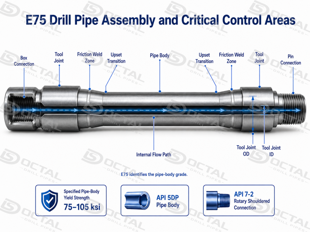
E75 Drill Pipe is manufactured to API 5DP, with a pipe-body yield-strength range of 75,000–105,000 psi and a minimum tensile strength of 100,000 psi. It is commonly used in conventional vertical wells, surface and intermediate sections, and low-dogleg drilling where the required tensile reserve and rotary load do not require the higher strength range of X95 or G105.
The final capacity of an API 5DP E75 Drill Pipe depends on the selected OD, nominal weight, wall thickness, upset type, tool joint OD and ID, and rotary shouldered connection. Octal Drill Pipes links the pipe-body heat number, heat-treatment lot, mechanical test, friction-weld NDT, thread gauging, and packing identity to each finished joint so the material, connection, and inspection records remain consistent with the approved specification.
E75 Drill Pipe Specifications and Supply Range
E75 drill pipe specifications must be released as one matched assembly rather than as separate selections of grade, outside diameter, and connection. For the same pipe OD, a change in nominal weight alters the wall thickness and pipe-body ID; the upset type determines the weld section and transition geometry; and the tool joint OD, ID, and connection control torsional capacity, hydraulic clearance, and drill string compatibility. Each configuration should therefore be tied to one approved data sheet covering the pipe body, upset, tool joint, connection, optional protection, inspection scope, and traceability records.
| Specification Item | Available or Required Information | Technical Significance |
|---|---|---|
| Base Standard | API Spec 5DP | Defines the manufacturing and acceptance basis |
| Pipe-Body Grade | E75 | Establishes the pipe-body mechanical-property class |
| Outside Diameter | Size-specific API 5DP configuration | Affects cross-sectional area, string weight, and handling |
| Nominal Weight | Size-specific lb/ft designation | Identifies the dimensional family of the pipe body |
| Wall Thickness | Determined by OD and nominal weight | Influences tensile, torsional, and pressure capacity |
| Length Range | R1, R2, or R3 | Defines handling length and drill string layout |
| Upset Type | IU, EU, or IEU where applicable | Provides the transition section for tool-joint welding |
| Connection Family | NC, IF, FH, or approved special connection | Transfers torque and maintains string compatibility |
| Tool Joint Configuration | OD, ID, pin, box, shoulder, and length | Controls connection strength and hydraulic clearance |
| Optional Features | Hardbanding, internal coating, surface treatment, and thread protectors | Addresses wear, pressure loss, galling, and transport protection |
| Inspection Scope | Mechanical, dimensional, weld-zone, tool-joint, and thread inspection | Confirms conformity of the finished assembly |
| Documentation | MTC, test records, heat and lot records, and packing list | Maintains product and document traceability |
Before production release, dimensional continuity should be checked from the pipe body through the upset and friction-weld transition to the tool joint and connection. A restricted tool joint ID can increase circulation pressure loss, an oversized tool joint OD can reduce annular clearance, and an unsuitable connection may limit torque capacity before the E75 pipe body reaches its strength limit. Final acceptance should reconcile the approved data sheet with the MTC, heat and lot records, weld-zone NDT, thread gauging, marking, and packing identity of the finished joint.
E75 Drill Pipe Mechanical Properties
E75 drill pipe is normally selected for conventional vertical wells, low-dogleg sections, and drilling strings where hook load, torque, and overpull do not require the higher strength range of X95 or G105.
Compared with X95 drill pipe, E75 provides a lower pipe-body yield range and is better suited to moderate-load drilling programs. The values below apply to the pipe body; tool joint strength, friction weld integrity, connection capacity, and remaining wall thickness must still be checked separately for the finished drill pipe assembly.
| Mechanical Property | API 5DP E75 Requirement | Technical Verification Point |
|---|---|---|
| Minimum Yield Strength | 75 ksi / 517 MPa | Verify the reported value by heat number and heat-treatment lot. |
| Maximum Yield Strength | 105 ksi / 724 MPa | Confirm that the result remains within the E75 yield-strength range. |
| Minimum Tensile Strength | 100 ksi / 689 MPa | Check the tensile test result and corresponding specimen identification. |
| Minimum Elongation | Calculated according to the API 5DP formula | Confirm the specimen cross-sectional area and calculated minimum value. |
| Pipe-Body CVN Impact Test | Specified when required by the applicable PSL, SR19, or project condition | Define the test temperature, specimen size, average energy, and minimum individual energy. |
Grade selection should be based on the complete load envelope rather than nominal strength alone. For an E75 drill string, tensile reserve, torque, dogleg severity, overpull allowance, connection rating, and remaining wall thickness should be reviewed together because the pipe body, weld transition, and tool joint do not carry load in the same way. This check is especially important for used pipe or mixed strings, where wear and dimensional mismatch can reduce the available operating margin before the material limit is reached.
E75 Drill Pipe Sizes
E75 drill pipe sizes must be reviewed as complete dimensional combinations rather than by outside diameter alone. For the same OD, different nominal weights produce different wall thicknesses and internal diameters, which change pipe-body cross-sectional area, circulating clearance, and available tensile and torsional margin. The selected upset, tool joint OD/ID, connection, and length must therefore correspond to the same approved API 5DP configuration.
| Specification Item | Required Information | Technical Significance |
|---|---|---|
| Pipe Body | OD, nominal weight, wall thickness, and ID | Defines pipe-body strength, weight, and flow area |
| Upset Type | IU, EU, or IEU | Matches the pipe body with the friction-weld section |
| Tool Joint | OD and ID | Balances connection strength and hydraulic clearance |
| Connection | NC, IF, FH, or specified special connection | Confirms torque transfer and string compatibility |
| Length Range | R1: 18–22 ft; R2: 27–30 ft; R3: 38–45 ft | Defines handling, transport, and tally length |
| Optional Features | Hardbanding and internal coating | Addresses external wear and internal service requirements |
Before the size is released, the pipe-body ID should be checked against the minimum tool joint ID to prevent an unnecessary internal restriction, while tool joint OD should be reviewed against annular clearance and wear allowance. The final data sheet should also confirm upset geometry, connection designation, finished joint length, hardbanding location, and internal coating so the delivered joint matches the drill string tally and mating components.
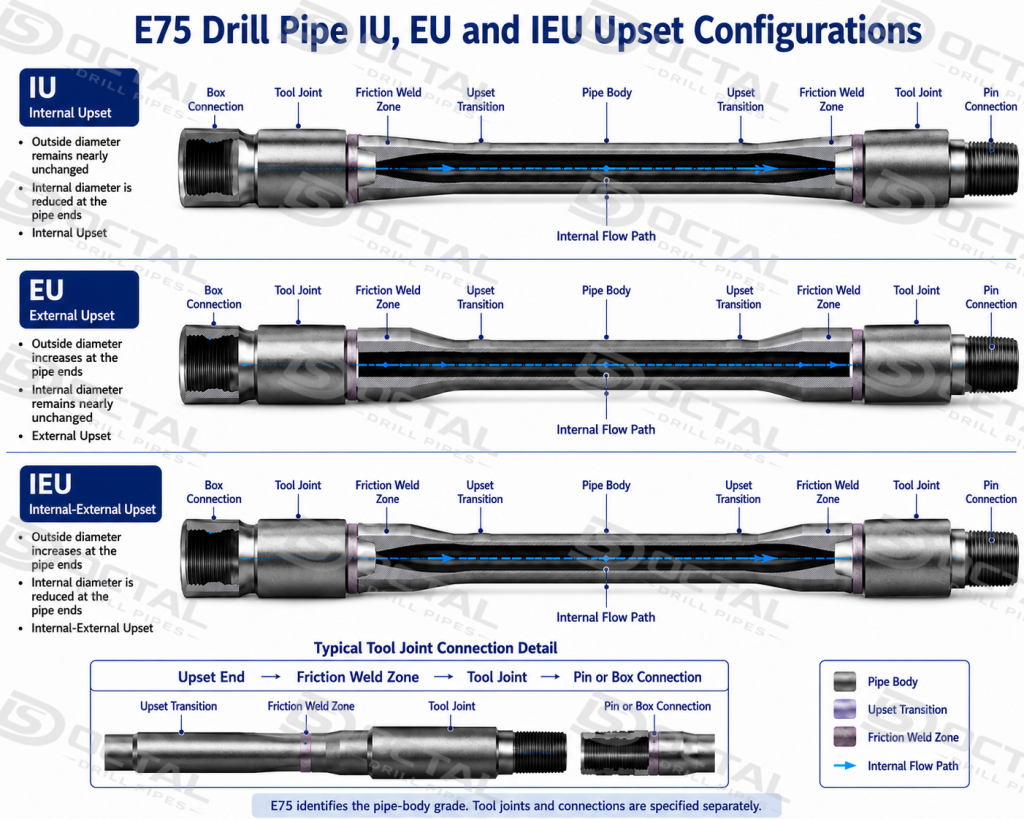
E75 Drill Pipe Connections and Upset Configuration
E75 drill pipe connections should be selected together with the pipe-body size, nominal weight, upset type, and tool joint dimensions. IU, EU, and IEU upset configurations may be used where they match the approved API 5DP dimensional combination, while NC, IF, FH, or specified rotary shouldered connections are selected according to drill string compatibility and required torque capacity.
| Configuration Item | Technical Check |
|---|---|
| Upset Type | Confirm IU, EU, or IEU against the pipe-body size and tool joint design |
| Connection | Verify the exact NC, IF, FH, or special connection designation |
| Tool Joint | Match tool joint OD and ID with connection strength and internal clearance |
| Thread Inspection | Check thread profile, shoulder condition, and API 7-2 gauge result |
| Protection | Confirm surface treatment and correct pin and box protectors |
The connection should not be selected from the E75 grade name alone. The approved configuration must align the pipe body, upset transition, tool joint, and rotary shouldered connection within the same technical data sheet.
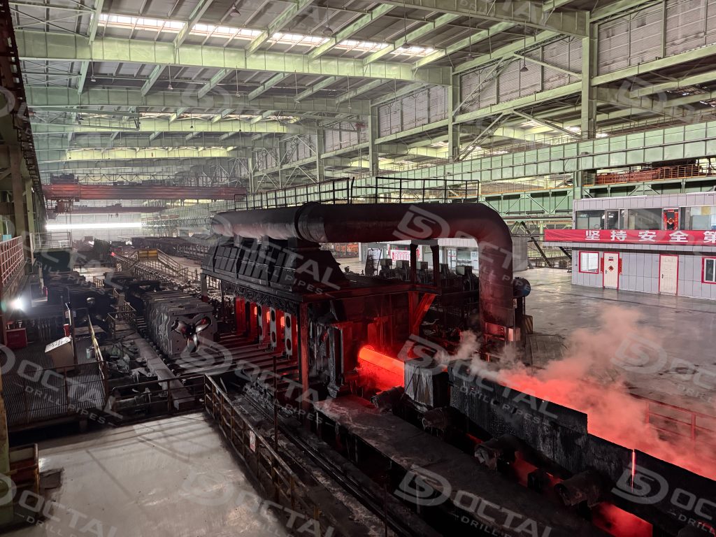
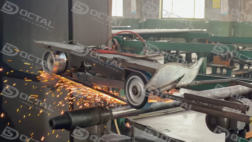
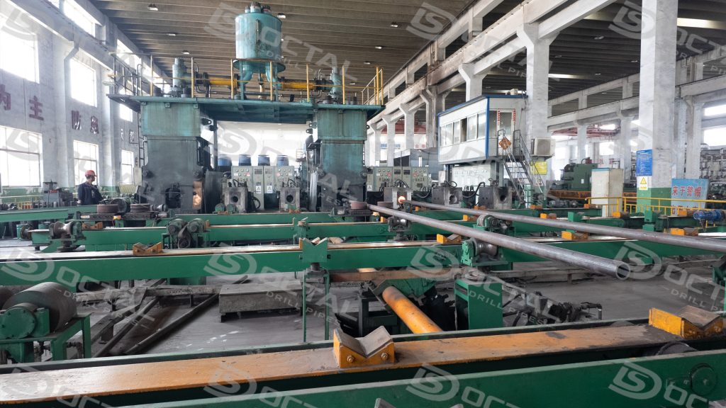
E75 Drill Pipe Manufacturing Process
E75 production must maintain the pipe body within the specified 75–105 ksi yield-strength range while preserving consistent properties through the upset transition. Because the pipe body and tool joint are heat treated separately, their material identities, heat-treatment lots, dimensions, and mechanical records must remain independent until friction welding. The approved manufacturing route should therefore control upset geometry, weld alignment, flash removal, tool joint OD/ID, and connection machining as one finished-joint configuration.
| Manufacturing Stage | E75-Specific Control | Required Production Record |
|---|---|---|
| Pipe-Body Heat Treatment | Control the heat-treatment cycle so the pipe body meets the E75 yield and tensile requirements | Heat-treatment lot and mechanical test report |
| End Upsetting | Maintain the approved IU, EU, or IEU geometry and transition profile | Upset dimensional record |
| Tool Joint Production | Match tool joint material, hardness, OD, ID, and connection to the E75 pipe-body configuration | Tool joint heat and inspection record |
| Friction Welding | Control alignment, weld transition, flash removal, and weld-zone integrity | Weld lot and NDT record |
| Thread Machining | Machine the specified rotary shouldered connection and verify the shoulder and gauge result | Thread inspection and gauging record |
| Final Release | Confirm grade marking, size, connection, protector, and document consistency | Final inspection report and packing list |
Production release should confirm that the heat-treatment lot represented by the mechanical tests matches the finished pipe marking, and that the upset transition remains compatible with the selected tool joint. After friction welding, axial alignment, weld-zone NDT, internal and external flash removal, shoulder condition, and API 7-2 thread gauging should be verified before coating, marking, and packing. The final joint record should link the pipe-body heat, tool-joint heat, weld lot, thread report, and packing identity without breaks in traceability.
E75 Drill Pipe Inspection and Traceability
Each finished E75 joint should remain connected to its pipe-body heat, heat-treatment lot, tool-joint record, friction-weld inspection, thread gauging, and final marking. The release file should allow the physical pipe or bundle to be traced back to the corresponding MTC and production records.
| Control Area | Key Verification | Release Record |
|---|---|---|
| Pipe Body | Grade, OD, wall thickness, and mechanical properties | MTC and mechanical test report |
| Friction Weld | Alignment, transition profile, and NDT acceptance | Weld-lot and NDT record |
| Tool Joint | OD, ID, hardness, and surface condition | Tool-joint inspection record |
| Connection | Thread profile, shoulder, and gauge result | Thread inspection report |
| Final Release | Marking, protectors, quantity, and bundle identity | Final report and packing list |
The complete inspection chain should read:
Pipe marking → Heat number → MTC → Heat-treatment lot → Mechanical test → Weld-zone NDT → Thread gauging → Packing list
Where E75 Drill Pipe Is Used
E75 drill pipe is used where the calculated operating loads can be carried by the selected pipe-body size, tool joint, and connection without requiring the higher yield range of X95 or G105.
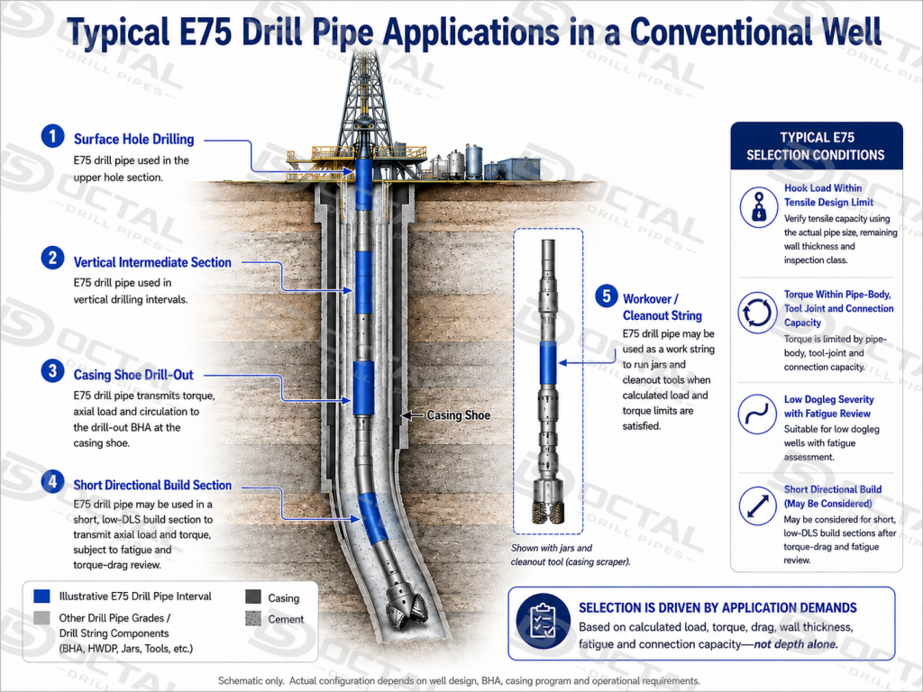
- Surface-hole drilling with a short suspended string
During conductor and surface-hole drilling, the drill string is still relatively short and accumulated drag is limited. E75 can be used for rotary drilling and circulation where hook load, mud weight, and required overpull remain below the allowable tensile capacity of the selected size and nominal weight.
- Vertical intermediate sections before the directional build
E75 is suitable while drilling a near-vertical intermediate section with stable rotary torque and no long high-angle interval below the rig floor. The grade is selected after confirming pick-up load, slack-off load, rotating torque, and the available margin for freeing the string.
- Drilling out casing shoes and cement inside a near-vertical well
E75 can be used for drilling out a shoe track, cement plug, or float equipment when the operation involves controlled weight on bit and defined rotary torque. Connection capacity and overpull allowance should be checked before the string is exposed to repeated stall, back-reaming, or heavy milling loads.
- Short sidetracks and low-angle directional sections
A short build or tangent section may use E75 where the planned dogleg severity does not create excessive cyclic bending at the upset and tool-joint transition. The review should include the number of rotations through the curved interval, not only the maximum inclination.
- Workover, wash-down, and cleanout operations
E75 drill pipe may be used for circulation, wash-down, scale removal, and controlled cleanout work where tensile load and rotary demand are known. Operations involving heavy fishing, high overpull, aggressive milling, or repeated jarring require a separate load review rather than automatic use of the same string.
- Conventional land drilling without long horizontal displacement
On a simple vertical or low-angle well, E75 may provide adequate capacity when the drill string is not subjected to sustained high torque and drag. The selected tool joint and connection must still carry the required make-up torque and downhole rotary torque.
Final grade selection should be based on calculated hook load, torque, drag, dogleg severity, overpull allowance, connection rating, and remaining wall thickness rather than well depth alone.
Why Choose Octal Drill Pipes
Octal Drill Pipes supports E75 Drill Pipe projects through coordinated technical review, production follow-up, inspection scheduling, documentation, and export release. This reduces handover gaps between pipe-body manufacturing, tool-joint production, connection machining, and final shipment preparation.
Before production, the approved data sheet is checked against the drilling program and mating drill-string components. During manufacturing, lot status, inspection hold points, third-party witness requirements, and document completion are tracked together, allowing the physical product and its technical file to move through release at the same pace.
For export delivery, pipe marking, thread protectors, bundle identification, packing lists, and shipment photographs are prepared to match the released configuration. This provides a clearer handover from factory to warehouse, port, and rig site, while reducing specification discrepancies and document mismatches.
FAQ
F1:Does E75 drill pipe have a fixed hook-load or overpull rating?
Q1:No. E75 defines the pipe-body strength grade, while allowable hook load and overpull depend on OD, wall thickness, wear condition, tool joint capacity, connection rating, and the combined effect of tension and torque. The operating limit must be calculated for the actual drill pipe configuration.
F2:Can E75 drill pipe be used in the same string as X95 or G105?
Q2:Yes, provided the connection, tool joint dimensions, make-up torque, internal clearance, and load distribution are compatible. The working limit of a mixed-grade string should be based on its weakest pipe-body or connection section, not on the highest grade installed.
F3:How does wall loss affect used E75 drill pipe capacity?
Q3:Wall loss reduces the pipe-body cross-sectional area and lowers tensile, torsional, internal-pressure, and collapse capacity. Used E75 drill pipe should therefore be evaluated from measured wall thickness, OD wear, inspection class, and current tool joint condition rather than its original nominal size.
F4:Is standard E75 drill pipe suitable for H₂S sour service?
Q4:Standard E75 grade alone does not confirm sour-service suitability. H₂S service requires a specified sour-service route such as SS75, together with applicable hardness limits, material control, and SSC resistance testing for the pipe body, tool joint, and weld zone.