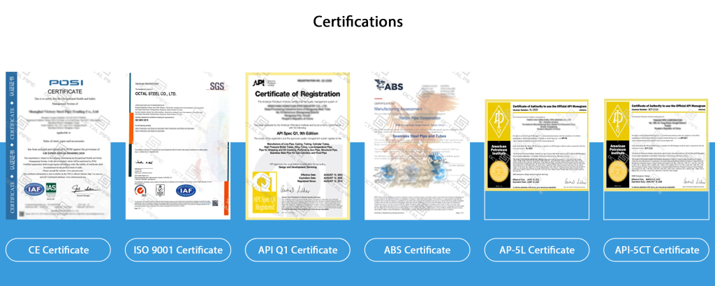
Heavy Weight Drill Pipe (HWDP) is a thick-wall rotary drill-stem element used mainly in the bottom-hole assembly (BHA) and in the transition between rigid drill collars and conventional drill pipe. It is manufactured either as an integral component machined from hot-rolled or forged alloy-steel bar, or as a welded assembly consisting of a heat-treated seamless alloy-steel tube and quenched-and-tempered tool joints. The increased wall section, long tool joints, and center upset or wear pad provide more mass and bending stiffness than standard drill pipe while retaining greater flexibility than a drill collar. Product requirements are covered by API Spec 7-1, while rotary-shouldered connection dimensions and gauging are controlled by API Spec 7-2.
Unlike heavy-wall or thick-wall drill pipe manufactured to API 5DP, API 7-1 HWDP has its own dimensional, material, connection, drift, inspection, marking, and traceability requirements. It is normally installed where a drilling program needs a controlled stiffness transition, additional distributed weight, or a tubular capable of operating under compressive and cyclic bending loads without introducing the same rigidity as a full drill-collar section. API specifically states that the two product categories should not be confused.
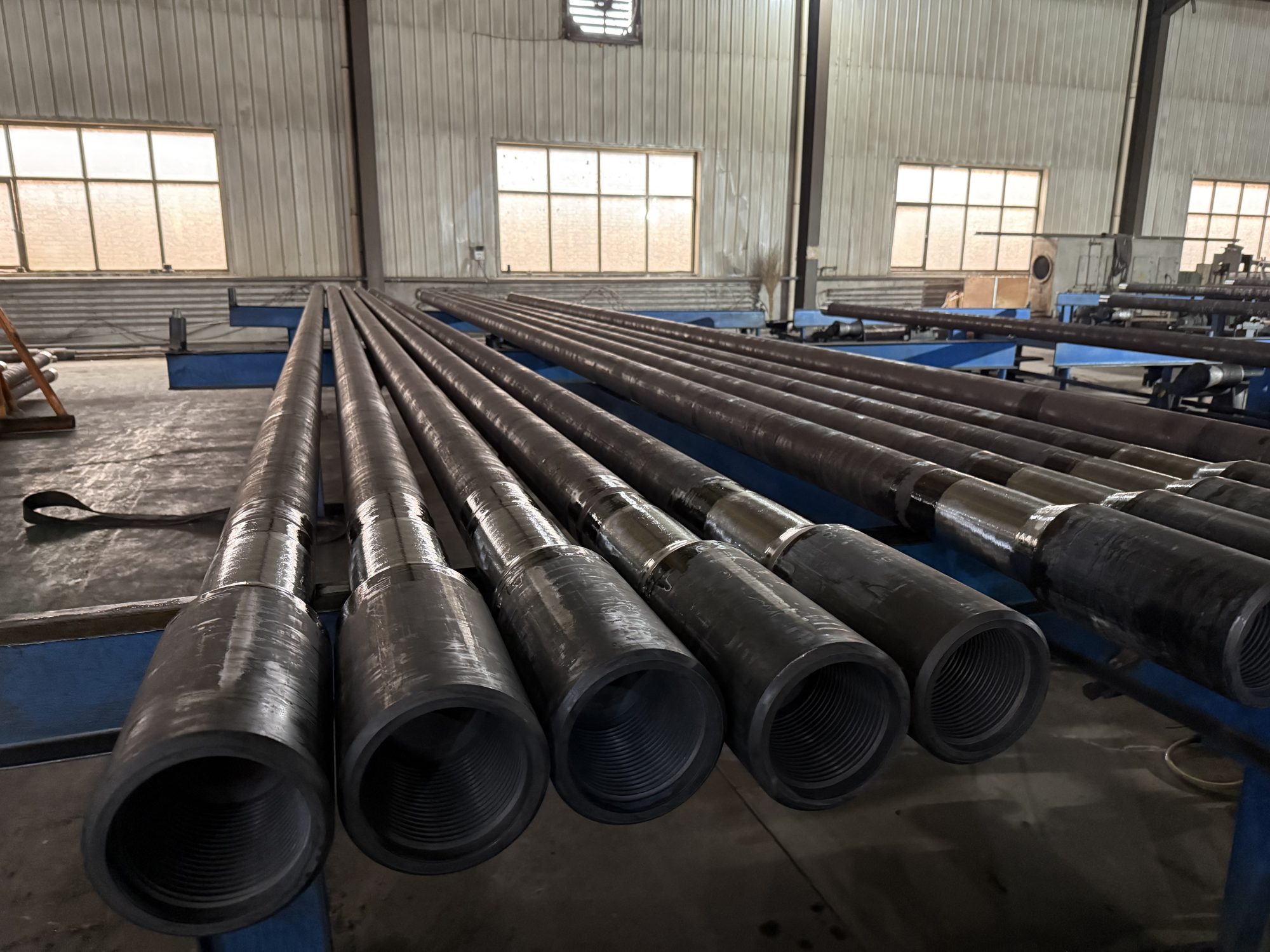
Octal Drill Pipes supplies welded, integral, standard, and spiral heavy weight drill pipe configurations for vertical, directional, horizontal, extended-reach, milling, under-reaming, and hole-opening operations. Final dimensions are matched to the BHA geometry, connection system, required internal clearance, hardbanding program, inspection level, and release-document requirements.
Heavy Weight Drill Pipe Specifications
The main heavy weight drill pipe specifications are not limited to nominal tube OD. A complete technical data sheet should define the tube bore, wall section, center upset, tool joint dimensions, connection, drift, assembly weight, hardbanding, length, material route, and inspection package.
| Specification Item | Typical Supply Range or Requirement |
| Product type | Welded HWDP or integral HWDP |
| External profile | Standard/slick, center-upset, spiral, full-spiral, or tri-spiral |
| Nominal tube OD | 2-7/8 in. to 6-5/8 in. |
| Common lengths | 30 ft or 31 ft; Range 2 and Range 3 configurations by project |
| Connections | NC26, NC31, NC38, NC40, NC46, NC50, 5-1/2 FH, 6-5/8 FH, or approved proprietary connection |
| Connection orientation | Box-up and pin-down unless otherwise specified |
| Welded body material | Heat-treated seamless alloy-steel tube |
| Tool joint material | Quenched-and-tempered forging, forged bar, or hot-rolled steel |
| Integral material | Hot-rolled or forged alloy-steel bar meeting the applicable drill-collar material requirements |
| Center section | Slick body, center upset, wear pad, or machined spiral profile |
| Bore inspection | Drift mandrel at least 3.05 m (10 ft) long |
| Thread inspection | API Spec 7-2 gauging or approved proprietary-connection procedure |
| Optional features | Hardbanding, internal plastic coating, cold-worked thread roots, pin stress-relief groove, box bore-back, make-and-break |
| Release documents | MTC, dimensional report, NDT records, hardness report, connection-gauge record, drift report, marking list, and packing list |
Public industry product ranges commonly cover approximately 2-7/8 in. through 6-5/8 in., with standard and spiral designs, API and double-shoulder connections, and optional internal coating or fatigue-control features.
Heavy Weight Drill Pipe Weight Chart
A heavy weight drill pipe weight chart must be read together with the tool joint OD and ID, center-upset geometry, connection, and joint length. Two joints with the same nominal tube OD can have different assembly weights because the connection bore, tool joint diameter, spiral profile, hardbanding, and overall length are different.
The following values are representative standard configurations. They are suitable for preliminary comparison, but the approved manufacturing data sheet should control final dimensions and shipment weight.
| Nominal Tube OD | Center Upset OD | Connection | Tool Joint OD × ID | Approx. Adjusted Weight | Approx. Weight per 31 ft Joint |
| 2-7/8 in. | 3-5/16 in. | NC26 | 3-3/8 × 1-1/2 in. | 17.26 lb/ft | 535 lb |
| 3-1/2 in. | 4 in. | NC38 | 4-3/4 × 2-1/4 in. | 23.48 lb/ft | 728 lb |
| 4 in. | 4-1/2 in. | NC40 | 5-1/4 × 2-9/16 in. | 29.92 lb/ft | 928 lb |
| 4-1/2 in. | 5 in. | NC46 | 6-1/4 × 2-3/4 in. | 41.45 lb/ft | 1,285 lb |
| 5 in. | 5-1/2 in. | NC50 | 6-5/8 × 3 in. | 50.38 lb/ft | 1,562 lb |
| 5-1/2 in. | 6 in. | 5-1/2 FH | 7-1/4 × 3-1/4 in. | 61.63 lb/ft | 1,911 lb |
| 6-5/8 in. | 7-1/8 in. | 6-5/8 FH | 8 × 4-1/2 in. | 71.43 lb/ft | 2,214 lb |
The values above are based on publicly listed standard HWDP assemblies and a nominal 31 ft joint. Spiral, large-bore, premium-connection, or integrally machined configurations can produce different weights.
HWDP Joint Weight Calculation and Verification
The basic estimate is:
Approximate joint weight = adjusted assembly weight per foot × actual joint length
This calculation does not automatically include thread protectors, transport frames, packing materials, or configuration-specific accessories. For logistics planning, the packing list should state:
- Actual joint length
- Actual net weight per joint
- Total quantity
- Bundle or frame weight
- Gross shipping weight
- Heat or traceability number for each joint
5 Inch Heavy Weight Drill Pipe Specs
5 in. heavy weight drill pipe is widely used in drill strings equipped with 5 in. drill pipe and NC50 connections, where it provides a practical balance of distributed weight, bending stiffness, and internal clearance. A typical configuration uses a 5 in. tube body with an NC50 rotary-shouldered connection, while the tool joint OD, tool joint ID, drift diameter, and bore profile must be matched to the adjacent drill pipe, drill collars, and downhole tools.
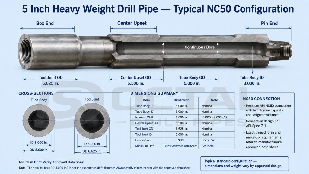
| 5 Inch HWDP Parameter | Typical Standard Configuration |
|---|---|
| Tube body OD | 5.000 in. |
| Tube body ID | 3.000 in. |
| Nominal wall thickness | 1.000 in. |
| Center upset OD | 5.500 in. |
| Connection | NC50 |
| Tool joint OD | 6.625 in. |
| Tool joint ID | 3.000 in. |
| Approx. adjusted weight | 50.38–50.49 lb/ft |
| Approx. 31 ft joint weight | About 1,560 lb |
| Common construction | Welded or integral |
| Optional profile | Standard, spiral, full-spiral, or tri-spiral |
| Optional features | Hardbanding, bore-back, stress-relief groove, cold-worked thread roots, internal coating |
Published 5 in. configurations show a 5 in. OD, 3 in. bore, 1 in. nominal wall, NC50 connection, and approximately 50.4 lb/ft assembly weight.
The make-up torque should not be selected from the words “5 inch NC50” alone. Tool joint OD and ID, remaining shoulder area, material strength, connection condition, thread compound friction factor, and the approved connection data sheet all affect the permitted torque.
Heavy Weight Drill Pipe Position in the Drill String
HWDP is commonly positioned above the drill collars or above other rigid BHA components. Its purpose is not simply to add weight. It creates an intermediate section between components with significantly different bending stiffness.
| Drill-String Component | Relative Wall and Stiffness | Main Function | Main Review Point |
|---|---|---|---|
| Conventional drill pipe | Thinner wall and more flexible | Transmits torque, axial load, and drilling fluid over the main string length | Pipe grade, wall, connection, fatigue history |
| Heavy weight drill pipe | Thick wall and intermediate stiffness | Moderates stiffness change, carries distributed weight, and operates in transition or compressive sections | Body ID, center upset, connection, bending exposure, hardbanding |
| Drill collar | Heavy and highly rigid | Provides near-bit stiffness, stabilization, and concentrated weight on bit | OD/ID, stiffness, neutral point, connection BSR |
A sudden change from a large, stiff drill collar to relatively flexible drill pipe increases bending stress in the transition zone. HWDP is placed between them to reduce the severity of that stiffness step. Industry drilling references also describe HWDP as stiffer than drill pipe but less stiff than drill collars, which is why it is used as a transition member.
HWDP does not independently guarantee longer fatigue life. Actual fatigue exposure still depends on:
- Dogleg severity
- Rotary speed
- Axial tension or compression
- Tool joint geometry
- Connection condition
- Drill-string buckling
- Wellbore contact
- Hardbanding condition
- Previous service and inspection history
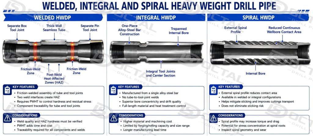
Heavy Weight Drill Pipe Types
Welded Heavy Weight Drill Pipe
Welded HWDP consists of a box tool joint, a thick-wall seamless tube, and a pin tool joint. The tool joints are normally joined to the tube by friction or inertia welding at enlarged end sections.
Under API Spec 7-1, the weld must be positioned in the upset section rather than in the transition radius. The weld design must provide a strength greater than the strength of the minimum tube section. Welding must follow a qualified procedure that includes post-weld heat treatment, and the surface hardness in the heat-affected zone must remain below 37 HRC.
Welded construction is suited to projects requiring:
- Multiple tube sizes and bores
- Different tool joint OD and ID combinations
- API or approved proprietary connections
- Long tool joints with future recut allowance
- Specific tube-body and tool-joint strength combinations
The main release points are weld alignment, post-weld heat treatment, HAZ hardness, weld-zone inspection, body-to-tool-joint traceability, and dimensional continuity through the bore.
Integral Heavy Weight Drill Pipe
Integral HWDP is machined from a single hot-rolled or forged alloy-steel bar. There is no friction-weld interface between the body and tool joints.
API Spec 7-1 requires integral HWDP material to meet the applicable drill-collar material requirements, with tensile properties corresponding to a drill collar of the same size as the HWDP tool joint diameter. In commercial production, modified 4145H alloy steel is commonly used, although the actual material specification must be confirmed from the MTC rather than assumed from the product name.
Integral construction is selected where the project requires:
- One-piece manufacture
- No tube-to-tool-joint weld interface
- Higher-strength body properties
- Small sizes where welded construction is impractical
- Special material or non-magnetic configurations
- Tight control of bore concentricity and body geometry
Its critical checks include bar cleanliness, heat-treatment uniformity, straightness, full-length NDT, trepanned-bore condition, bore match point, thread gauging, and drift clearance.
Spiral Heavy Weight Drill Pipe
Spiral HWDP describes the external geometry, not necessarily a separate manufacturing route. A spiral profile can be applied to an integral or welded assembly.
The machined spiral section reduces the continuous contact area between the tubular and the wellbore. This can assist with:
- Reducing broad wall contact
- Managing differential-sticking exposure
- Maintaining annular flow paths
- Reducing drag in selected well sections
- Controlling distributed contact in directional drilling
A spiral profile does not eliminate sticking or hole-cleaning problems. Mud properties, cuttings beds, wellbore geometry, differential pressure, rotation, and circulation still control the operating risk. Public product ranges include standard, tri-spiral, and full-spiral designs with different assembly weights.
HWDP Materials and Mechanical Properties
Material requirements should be reviewed separately for the tube body, tool joints, integral bar, and weld zone. Writing only “4145H HWDP” does not accurately describe every welded assembly.
| Component | Material Route | Key API 7-1 Requirement or Review Point |
|---|---|---|
| Welded tube body | Normalized, normalized and tempered, or quenched-and-tempered seamless alloy-steel tube | Minimum tensile strength 655 MPa (95,000 psi) |
| Welded tube body | Same as above | Minimum yield strength 379 MPa (55,000 psi) |
| Welded tube body | Same as above | Minimum elongation 18% |
| Tool joint | Forging, forged bar, or hot-rolled steel | Quenched and tempered |
| Tool joint impact test | Heat or heat-treatment lot control | Average of three specimens at least 54 J (40 ft-lb); no single value below 47 J (35 ft-lb) |
| Integral body | Hot-rolled or forged alloy-steel bar | Drill-collar material requirements for the corresponding tool joint diameter |
| Weld zone | Qualified welding route and PWHT | HAZ surface hardness below 37 HRC |
The tube-body mechanical values and weld-zone hardness limit are explicit API requirements. Tool joint impact testing is also tied to heat and heat-treatment lot control rather than a generic material certificate with no lot relationship.
Common commercial material combinations include modified AISI 1340 alloy steel for a standard welded tube body and modified AISI 4140H or 4145H for tool joints. Integral assemblies are commonly machined from modified 4145H bar. These are typical manufacturing choices, not a substitute for the project material specification or actual MTC values.
HWDP Connections and Internal Clearance
Typical API connection combinations include:
| Nominal HWDP Size | Common Connection | Typical Tool Joint OD |
|---|---|---|
| 2-7/8 in. | NC26 | 3-3/8 in. |
| 3-1/2 in. | NC38 | 4-3/4 in. |
| 4 in. | NC40 | 5-1/4 in. |
| 4-1/2 in. | NC46 | 6-1/4 in. |
| 5 in. | NC50 | 6-5/8 in. |
| 5-1/2 in. | 5-1/2 FH | 7-1/4 in. |
| 6-5/8 in. | 6-5/8 FH | 8 in. |
The connection name alone does not define the complete geometry. The same connection designation can be supplied with different tool joint IDs, ODs, bore-back details, or remaining shoulder areas.
API Spec 7-1 requires HWDP connections to be supplied box-up and pin-down and to meet the dimensional and gauging requirements of API Spec 7-2. Proprietary connections are outside the API connection-design scope and require their own licensed drawing, gauge procedure, and performance data.
Drift Diameter and Tool Passage
The drift diameter confirms the minimum clear bore through the complete HWDP assembly, including both tool joints, the tube body, and the center section. A large tube-body ID alone does not guarantee tool passage because the tool joint bore or the bore match point may form the smallest restriction. The specified drift must therefore be checked against the OD of MWD/LWD tools, survey instruments, drop balls, darts, and fishing tools.
All welded and integral HWDP bores covered by API Spec 7-1 must be checked with a drift mandrel at least 3.05 m (10 ft) long. Where the bore is drilled from both ends, the bore match point must be located beneath the center upset or wear pad.
The drift diameter should be reviewed against:
- MWD or LWD tool OD
- Survey instrument OD
- Drop-ball or dart diameter
- Fishing-tool passage
- Internal coating allowance
- Bore mismatch at the center section
- Tool joint ID
- Connection bore-back
The smallest restriction may be located in the tool joint rather than the nominal tube body. A large tube ID does not prove that the complete assembly has the required through-bore.
Fatigue-Control and Wear-Control Features
Pin Stress-Relief Groove and Box Bore-Back
Stress-relief contours can reduce local stress concentration near the pin shoulder and the base of the box thread. They are optional features and should be included in the project specification when the connection is exposed to significant cyclic bending.
API also notes that stress-relief features slightly reduce pin cross-sectional area and connection section modulus. Where unusually high tensile loads are expected, the effect on connection capacity should be calculated rather than ignored.
Cold-Worked Thread Roots
Cold working introduces compressive residual stress at the thread root and can improve resistance to fatigue initiation at this high-stress location. API Spec 7-1 treats cold working as an optional requirement that must be specified.
Connections are gauged before cold working, and the appropriate CW marking is applied after the process.
Phosphate Treatment
Zinc, manganese, or combined zinc-and-manganese phosphate treatment is applied to the threads and sealing shoulders after final gauging. Its purpose is to reduce galling during make-up and break-out.
Hardbanding
Hardbanding can be applied to tool joints and to the raised center upset or wear pad. It protects the base material from abrasive wear, but the alloy type and geometry should also be compatible with the casing-wear program.
Unless otherwise specified, API Spec 7-1 lists the following hardbanding thicknesses:
| Location | Nominal Thickness and Tolerance |
|---|---|
| Tool joint | 2.4 mm +0.8/−0.8 mm |
| Center upset or wear pad | 2.4 mm +1.6/−0.8 mm |
Hardbanding welding procedures and personnel are qualified in accordance with the applicable requirements of ASME BPVC Section IX, with PQR and qualification records maintained by the manufacturer.
HWDP Applications by Drilling Condition
Transition Above the Bottom-Hole Assembly
In a vertical or moderately deviated well, HWDP is installed above the drill collars to reduce the abrupt stiffness change at the top of the BHA. This section experiences repeated bending as the drill string rotates through wellbore curvature.
The selection review should cover:
- Drill collar OD and ID
- Drill pipe OD, weight, and grade
- HWDP bending stiffness
- Number of HWDP joints
- Dogleg severity
- Rotary speed
- Neutral-point position
- Connection fatigue features
Directional and High-Angle Drilling
In a build, hold, or drop section, the drill string experiences combined rotation, bending, wall contact, torque, and axial load. HWDP provides greater bending compliance than drill collars while carrying more distributed weight than conventional drill pipe.
The important control point is not simply “use more HWDP.” The number and position of the joints must be checked against torque-and-drag results, buckling mode, planned dogleg severity, and BHA directional response.
Horizontal and Extended-Reach Sections
In long lateral sections, part of the drill string may be placed in compression to transfer force toward the bit. The engineering review must control sinusoidal or helical buckling, wall contact, connection fatigue, and internal hydraulic area.
Spiral HWDP can reduce continuous contact area, but it does not replace proper hole cleaning, mud design, circulation, rotation, and cuttings-bed management.
Milling, Under-Reaming, and Hole Opening
Milling and hole-opening assemblies need sufficient distributed mass and compression to maintain tool engagement. HWDP can provide this loading without extending a highly rigid drill-collar section farther up the work string.
Public technical product literature identifies milling, under-reaming, hole opening, directional control, and compressive loading as common HWDP duties.
Heavy Weight Drill Pipe Manufacturing Process
Welded HWDP Manufacturing Route
| Production Stage | Main Control Point |
|---|---|
| Tube manufacture and heat treatment | Chemistry, mechanical properties, wall, OD/ID, straightness |
| Tool joint manufacture | Forging or bar identity, quench and temper, hardness, impact properties |
| Component NDT | Surface and internal defect examination |
| End machining | Weld upset geometry and alignment surfaces |
| Friction or inertia welding | Weld position, flash control, process parameters |
| Post-weld heat treatment | Weld strength and HAZ hardness below 37 HRC |
| Flash removal and finish machining | Bore continuity and smooth transition |
| Connection threading | Thread form, taper, lead, shoulder, bevel, surface finish |
| API 7-2 gauging | Gauge identity, calibration status, standoff record |
| Thread-root treatment | Cold working when specified |
| Phosphate treatment | Applied after final gauging |
| Hardbanding | Alloy, placement, thickness, cracking inspection |
| Final dimensional inspection | Tube, upset, tool joint, length, alignment |
| Drift test | Minimum 10 ft mandrel and specified drift diameter |
| Marking and release | Heat identity, traceability ID, API marking, packing list |
Integral HWDP Manufacturing Route
| Production Stage | Main Control Point |
|---|---|
| Alloy-steel bar receipt | Heat number, chemistry, cleanliness, initial NDT |
| Full-length heat treatment | Mechanical uniformity and hardness |
| Straightening | Full-length straightness |
| Trepanning or boring | Bore alignment, concentricity, match point |
| External machining | Tool joints, body section, center upset, spiral profile |
| Full-length inspection | Surface and internal discontinuities |
| Threading and gauging | API 7-2 or approved proprietary connection procedure |
| Drift test | Complete bore clearance |
| Hardbanding and coating | Geometry, thickness, adhesion, final inspection |
| Marking and document release | Heat-to-joint traceability |
Dimensional and Weld Alignment Control
For welded HWDP, API Spec 7-1 controls the alignment between the tube and tool joint axes.
| Alignment Item | Maximum Limit |
|---|---|
| Angular misalignment, size 4 in. and smaller | 10 mm/m or 0.010 in./in. |
| Angular misalignment, larger than 4 in. | 8 mm/m or 0.008 in./in. |
| Parallel misalignment | 3.2 mm or 0.125 in. TIR |
The weld is positioned inside the upset area rather than in the radius between the tube and tool joint taper. This matters because poor alignment or an incorrectly located weld introduces cyclic bending and local stress concentration during rotation.
Inspection and Traceability
A product certificate is useful only when it can be traced to the actual HWDP joint. API Spec 7-1 requires procedures that maintain heat identity and link the tool joints and body to the relevant chemical analysis and specified mechanical test results.
| Inspection or Record | How It Is Checked | What It Confirms | Risk Controlled |
|---|---|---|---|
| Material Certificate and Chemical Analysis | Tube bodies, tool joints, and integral bars are identified by heat number and checked against the specified chemical composition. | Material grade, heat number, and alloy composition. | Material substitution, mixed heats, or incorrect alloy. |
| Tensile Test | A specimen from the applicable heat-treatment lot is pulled to failure after final heat treatment. | Yield strength, tensile strength, and elongation. | Insufficient strength or incorrect heat treatment. |
| Charpy V-Notch Impact Test | Three tool-joint specimens are tested at the specified temperature. For full-size specimens, the average shall be at least 54 J, with no individual result below 47 J. | Impact energy, specimen orientation, temperature, heat, and lot. | Low toughness and brittle-fracture exposure. |
| Hardness Test | Hardness readings are taken from tool joints, body areas, and each welded heat-affected zone. Weld-zone surface hardness shall be below 37 HRC. | Heat-treatment consistency and weld-zone condition. | Excessive hardness, brittle HAZ, or uneven heat treatment. |
| UT or Equivalent Internal Inspection | Qualified ultrasonic equipment scans the tube, integral bar, or tool-joint material using calibrated reference standards. | Internal material continuity and indication acceptance. | Internal cracks, laminations, inclusions, or shrinkage. |
| MPI or Equivalent Surface Inspection | Tool joints, upsets, machined transitions, and specified weld areas are magnetized and checked for relevant indications. | Surface and near-surface condition. | Cracks around threads, shoulders, upsets, and weld transitions. |
| Friction-Weld Zone Inspection | Weld position, flash removal, alignment, post-weld heat treatment, HAZ hardness, and required NDT are reviewed. | Weld process, alignment, hardness, and release status. | Poor bonding, weld offset, hard zones, or local stress concentration. |
| Dimensional and Alignment Report | OD, ID, wall section, center upset, tool-joint dimensions, overall length, straightness, and weld alignment are measured with calibrated tools. | Actual dimensions and assembly geometry. | Fit-up problems, restricted bore, handling issues, or eccentric loading. |
| Connection-Gauge Report | Pin and box connections are inspected with calibrated API Spec 7-2 gauges or an approved proprietary procedure. | Thread form, taper, standoff, shoulder, bevel, and connection identity. | Connection mismatch, improper make-up, galling, or shoulder interference. |
| Full-Length Drift Test | A drift mandrel at least 3.05 m (10 ft) long is passed through both tool joints, the tube body, and the center section. | Minimum continuous through-bore. | Obstruction of MWD/LWD tools, balls, darts, or fishing tools. |
| Hardbanding Inspection | Alloy, location, band width, thickness, profile, surface condition, and visible cracking are checked after application. | Correct hardbanding placement and acceptable finish. | Rapid wear, excessive buildup, cracking, or casing damage. |
| Marking, Packing List, and Lot Map | Each joint identification is linked to its material heat, weld record, inspection status, bundle, length, and weight. | Joint-to-document and joint-to-shipment traceability. | Document mismatch, mixed lots, or loss of traceability after packing. |
API-compliant marking includes the manufacturer identification, tube diameter, connection designation, API 7-1, and a traceability identification. Marking must not be placed in highly stressed areas such as the weld line or the transition radius.
Inspection of Used HWDP
A new-product MTC does not confirm the remaining condition of a used HWDP joint. Used drill-stem elements should be inspected and classified under the specified service inspection program.
API RP 7G-2 covers inspection levels, personnel qualification, inspection methods, apparatus calibration, imperfection evaluation, and marking for used drill-stem elements, including HWDP. The current listed edition is the second edition dated October 2020.
Typical used-HWDP review areas include:
- Remaining tool joint OD
- Remaining center-upset OD
- Body wall and wear
- Thread and shoulder damage
- Fatigue cracking
- Hardbanding condition
- Washout or internal erosion
- Straightness
- Bore obstruction
- Previous recut history
- Updated inspection marking
HWDP Specification Checklist
A complete technical specification should provide the following information before production release:
| Required Information | Example |
|---|---|
| Construction | Welded or integral |
| External profile | Standard, spiral, full-spiral, or tri-spiral |
| Tube OD and ID | 5 × 3 in. |
| Nominal wall | 1.000 in. |
| Length | 31 ft nominal |
| Connection | NC50 |
| Tool joint OD and ID | 6-5/8 × 3 in. |
| Connection orientation | Box-up, pin-down |
| Center upset or wear pad | 5-1/2 in. OD |
| Hardbanding | Alloy, locations, raised or flush, thickness |
| Internal coating | Type and coated length |
| Fatigue features | Pin SRG, box bore-back, cold-worked roots |
| Service condition | Vertical, directional, horizontal, milling, sour, geothermal |
| Internal clearance | Required minimum drift and tool passage |
| Inspection standard | API 7-1, API 7-2, API RP 7G-2, NS-1, DS-1, or project ITP |
| Third-party inspection | Hold, witness, review, and release points |
| Required documents | MTC, NDT, hardness, CVN, gauges, drift, marking, packing list |
Heavy Weight Drill Pipe for Sour Service
Standard API 7-1 conformity does not independently establish resistance to sulfide stress cracking in an H₂S environment. Sour-service HWDP requires a separate review of:
- H₂S partial pressure
- Temperature
- Chloride concentration
- Drilling-fluid chemistry
- Material grade
- Pipe-body hardness
- Tool joint hardness
- Weld-zone hardness
- SSC qualification method
- NACE TM0177 testing where specified
- Lot-specific test and heat-treatment records
Commercial drilling-tool manufacturers provide separate HWDP material grades for sour or critical service, which confirms that standard and H₂S-qualified material routes should not be treated as interchangeable.
For welded sour-service HWDP, the tube body, tool joints, and friction-weld zone should be reviewed separately. A low hardness value on one component does not establish the SSC resistance of the complete assembly.
FAQ
What is Heavy Weight Drill Pipe?
Heavy Weight Drill Pipe is an intermediate drill-stem component with a thick-wall body, long tool joints, and usually a center upset or wear pad. It provides more weight and stiffness than conventional drill pipe but remains more flexible than a drill collar.
Is HWDP drill pipe the same as API 5DP heavy-wall drill pipe?
No. The phrase HWDP drill pipe is sometimes used loosely, but API Spec 7-1 HWDP is a distinct rotary drill-stem element. API 7-1 specifically states that it should not be confused with heavy-wall or thick-wall drill pipe manufactured to API 5DP.
What is the difference between HWDP and a drill collar?
A drill collar is heavier and more rigid and is used mainly to provide near-bit stiffness and concentrated weight on bit. HWDP is lighter and more flexible, so it is commonly used as a transition member or as a distributed compressive-load component above the BHA.
What are the most common heavy weight drill pipe sizes?
Common sizes include 2-7/8, 3-1/2, 4, 4-1/2, 5, 5-1/2, and 6-5/8 in. The connection normally changes with the nominal size, from NC26 on smaller products to NC50, 5-1/2 FH, or 6-5/8 FH on larger assemblies.
Why do two 5 inch HWDP joints have different weights?
The weight changes with the tube ID, wall thickness, tool joint OD and ID, connection, center-upset geometry, spiral profile, hardbanding, and actual length. The nominal “5 inch” designation identifies the tube OD, not the complete assembly geometry.