
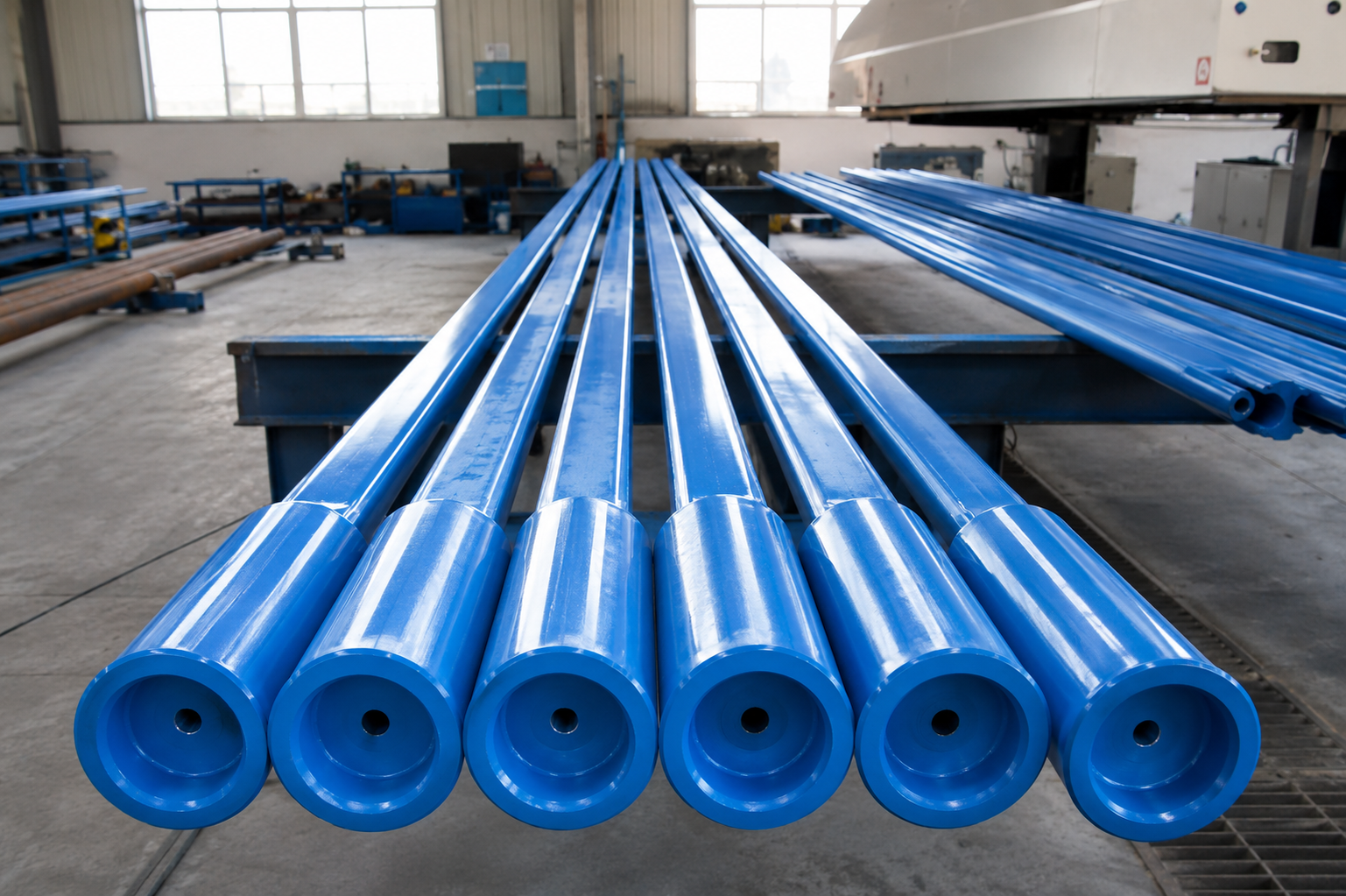
Square Kelly is an API Spec 7-1 rotary drill stem element commonly manufactured from a full-length AISI 4145H Modified chromium-molybdenum alloy-steel bar. The bar is quenched and tempered through its full length to develop the section strength, toughness and hardness consistency required for a component exposed to rotary torque, axial load, bending, impact and repeated sliding contact with the kelly bushing. After heat treatment, the bar is straightened and checked for runout, then deep-hole bored, gun drilled or trepanned to form the continuous drilling-fluid passage. The outside body is subsequently rough machined, and four drive flats are precision milled to establish the specified across-flats, across-corners, straightness and twist requirements. The upper and lower ends are finished with the required rotary shouldered connections and gauged in accordance with the applicable API Spec 7-2 requirements and approved manufacturing drawing.
In a conventional rotary-table drilling system, the square drive section passes through a matching kelly bushing, transmitting rotary-table torque to the drill string while allowing the kelly to move vertically as drilling advances. Its central bore maintains drilling-fluid circulation, while the drive geometry, bore alignment, remaining wall thickness and end-connection configuration determine compatibility with the installed rig, swivel-side equipment, saver sub and drill-pipe string.
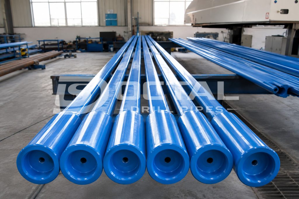
Octal Drill Pipes supplies square kelly drill pipe configurations with square or hexagonal drive profiles, specified internal bores, upper left-hand connections and lower right-hand rotary shouldered connections. Each order should be reviewed against the rig arrangement, kelly bushing profile, drill-string connection and approved dimensional drawing rather than selected by nominal size alone.
Representative Square Kelly Supply Range
The following ranges summarize commonly published oilfield kelly configurations. They are reference values only. Final dimensions must follow the approved manufacturing drawing and purchase order.
| Supply Item | Representative Range or Configuration |
| Nominal square sizes | Approximately 2-1/2 in. to 5-1/4 in. |
| Nominal hexagonal sizes | Approximately 3 in. to 6 in. |
| Common overall length | 40 ft |
| Extended configurations | 54 ft available for selected sizes |
| Common drive-section length | 37 ft or 51 ft, depending on overall length |
| Typical upper connection | 6-5/8 REG LH or 4-1/2 REG LH |
| Typical lower connections | NC26, NC31, NC38, NC46, NC50, NC56 or 5-1/2 FH, depending on size |
| Typical bore range | Selected according to kelly size and lower connection |
| Drive profile | Square or hexagonal |
| Thread protection | Pressed-steel or heavy-duty thread protectors |
| Transport protection | Steel-cased scabbard or equivalent protective packing |
A quoted nominal size should not be used as a substitute for the dimensional schedule. For example, two kellys with the same nominal drive size may have different bores, lower connections, upset ODs or overall lengths.
Square Kelly Function and Power Transmission in the Drill String
A conventional rotary-table system transfers power through a defined mechanical path:
Rotary table → master bushing → kelly bushing → square drive section → lower connection or saver sub → drill pipe → drill bit
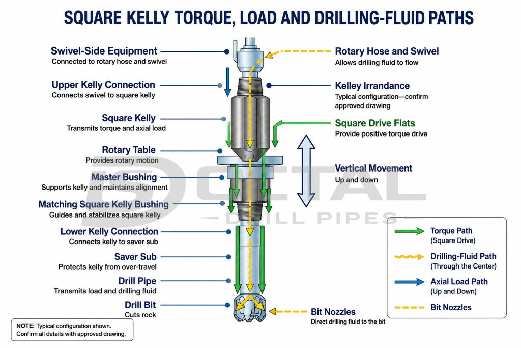
The inside profile of the kelly bushing matches the square or hexagonal outside profile of the kelly with sufficient operating clearance for vertical travel. Contact between the bushing and the drive flats transmits torque. As the bit advances, the kelly slides downward through the bushing while continuing to rotate the string.
The central bore forms part of the drilling-fluid circulation path. Fluid passes through the kelly, saver sub and drill pipe before reaching the bit nozzles. The bore must therefore remain continuous through the end connections, upset sections and drive body.
When the available kelly travel is used up, drilling stops temporarily and another drill-pipe joint is added to the string. The kelly is then raised and drilling resumes. This operating cycle distinguishes a traditional kelly system from a top drive, which applies rotation from a traveling drive unit above the drill string.
Further down the drill string, heavy weight drill pipe serves as a stiffness-transition member above the drill collars, while neither component replaces the kelly’s surface-drive function.
Square Kelly and Drill Pipe Perform Different Functions
Square Kelly and conventional API 5DP drill pipe are distinct drill-stem components governed by different API specifications and designed for different positions and functions within the drilling system.
| Review Point | Square Kelly | Drill Pipe |
| Primary standard | API Spec 7-1 | API Spec 5DP |
| Position | Top of a conventional rotary drill string | Repeated joints throughout the drill string |
| Main function | Transfers rotary-table torque through an external drive profile | Transmits axial load, torque and drilling fluid between threaded joints |
| External shape | Square or hexagonal drive section | Round pipe body |
| Construction | Machined alloy-steel bar with a central bore | Pipe body with upset ends and welded tool joints |
| Rig interface | Runs through a matching kelly bushing | Handled by slips, elevators and drill-string connections |
| Typical length logic | Selected for rig and kelly travel requirements | Commonly supplied as Range 2 or Range 3 drill pipe |
| Connection review | Upper and lower ends may have different hand and connection types | Pin and box tool joints form repeatable drill-pipe joints |
For broader drill-string context, the drill pipe, HWDP and drill collar comparison explains how the main string, stiffness-transition section and lower BHA perform separate mechanical functions.For quotation and inspection, the order should specify the kelly drive profile, bore size, overall length, upper and lower connection types, and matching kelly bushing dimensions. These details determine whether the kelly can transmit torque, maintain drilling-fluid flow, and fit the rotary-table system correctly.
Square and Hexagonal Kelly Configurations
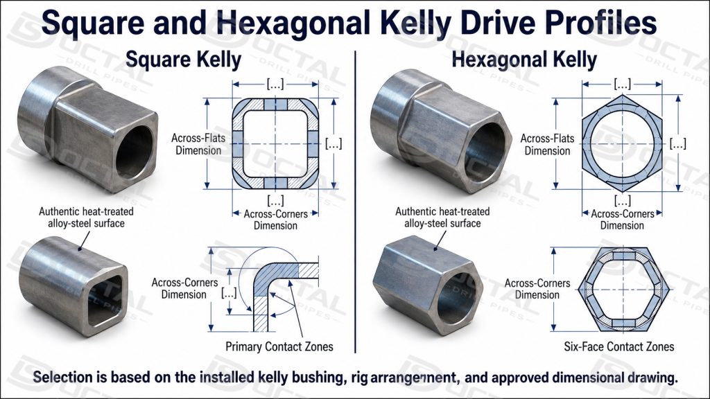
Square and hexagonal kellys are both used in conventional rotary-table drilling systems, where the drive profile passes through a matching kelly bushing to transmit torque while allowing vertical movement. Although they perform the same basic functions, the two configurations differ in external geometry, dimensional control, manufacturing route and wear characteristics. Selection is therefore based on the installed rotary equipment, bushing profile and approved dimensional requirements.
| Feature | Square Kelly | Hexagonal Kelly |
| External drive profile | Four flats | Six flats |
| Matching equipment | Square-profile kelly bushing | Hexagonal-profile kelly bushing |
| Main dimensional checks | Across flats, across corners and corner geometry | Across flats, across corners and six-face geometry |
| Typical manufacturing route | Forged or precision-machined drive section | Commonly precision machined from heat-treated bar |
| Selection driver | Existing rig and bushing configuration | Existing rig and bushing configuration |
| Wear review | Flats, corners and local contact marks | Flats, corners and distributed contact marks |
The purchase specification should identify the exact profile and approved drawing. “Square” or “hexagonal” alone is not enough to establish operating clearance or interchangeability.
Square Kelly Structure and Connection Arrangement
A complete API 7-1 square kelly normally contains five controlled areas.
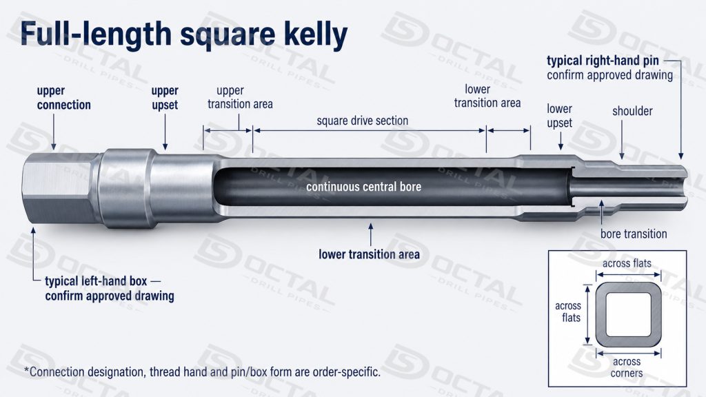
Upper Connection and Upset
The upper end commonly uses a left-hand box connection compatible with the swivel-side equipment or upper kelly arrangement. The connection designation, upset OD, bevel diameter, shoulder condition and bore must be stated in the purchase order.
Left-hand rotation should never be inferred from the connection name alone. The order and drawing should identify the connection and thread hand explicitly.
Drive Section
The drive section contains the square or hexagonal flats that contact the kelly bushing. Critical dimensions include:
- drive-section length;
- across-flats dimension;
- across-corners dimension;
- corner radius or approved profile;
- straightness;
- surface condition;
- local wear allowance.
Small dimensional errors can cause binding, excessive clearance, impact loading or uneven contact with the bushing.
Internal Bore
The bore carries drilling fluid through the complete kelly. Bore diameter alone does not confirm adequate wall thickness. The bore axis must also be controlled relative to the external drive profile and both upset sections.
Inspection should confirm:
- minimum specified bore;
- continuous internal passage;
- bore alignment;
- remaining wall around the bore;
- internal surface condition;
- transition into the end sections.
Lower Connection and Upset
The lower end commonly uses a right-hand pin connection that connects to a saver sub or the next drill-string component. Connection selection depends on the actual drill-pipe tool-joint configuration and should include the connection designation, OD, ID, shoulder geometry and approved make-up data.
Transition Areas
Changes from the upset ends to the drive body must be machined without sharp discontinuities that could increase local stress. Tool marks, abrupt section changes and mechanical damage in these areas require close visual and surface examination.
Applicable API Standards for Kellys and Connections
API Spec 7-1
API Spec 7-1 covers the technical delivery requirements for square and hexagonal kellys as rotary drill stem elements. The purchase specification should identify the applicable edition, product configuration, material requirements, dimensions, inspection scope and documentation.
A kelly is not classified as conventional API 5DP drill pipe. Its drive body, central bore and overall product requirements are reviewed under API Spec 7-1 and the approved manufacturing drawing.
API Spec 7-2
Where the upper or lower end uses an API connection, rotary shouldered connection threading and gauging should be reviewed against API Spec 7-2 and the specified connection drawing.The inspection normally confirms:
- connection designation and hand;
- thread form and critical dimensions;
- gauge standoff;
- pin or box condition;
- sealing shoulder condition;
- working-gauge calibration status; and
- any specified stress-relief, bore-back or surface-treatment requirements.
API RP 7G-1 and API RP 7G-2
API RP 7G-1 provides performance-property references and operating guidance for drill stem elements, including kellys. It supports engineering review of load capacity and service limits but does not replace the manufacturing and delivery requirements of API Spec 7-1.
API RP 7G-2 applies to the inspection and classification of drill stem elements after service. New-kelly factory acceptance should therefore be based on API Spec 7-1, the purchase specification and approved drawings, while field inspection of a used kelly should follow the applicable API RP 7G-2 inspection level and acceptance criteria.
Kelly Material, Heat Treatment and Through-Section Properties
AISI 4145H Modified is one commonly specified chromium-molybdenum alloy-steel route for square and hexagonal kelly manufacture. Its hardenability makes it suitable for the relatively large bar sections used in highly loaded drill stem components, where strength and toughness must be controlled beyond the machined surface.
The starting material may be supplied as forged or rolled bar and is normally quenched and tempered before final machining. Full-length heat treatment is used to establish the required mechanical properties through the working section, including the drive flats, corner regions, central bore and connection ends.
Material acceptance should be based on the purchase specification and approved manufacturing drawing. The traceability package should link the finished kelly to the steel heat number, heat-treatment lot, mechanical-test results, hardness records and applicable inspection reports.
Where hardness or Charpy impact requirements are specified, the order should also define the acceptance range, test temperature, specimen size and orientation, sampling location and reporting basis. Typical supplier values should not be presented as universal API acceptance limits.
The material certificate should confirm the actual steel grade, heat number, chemical analysis, heat-treatment condition and reported mechanical properties. Supporting heat-treatment and test records should remain traceable to the finished kelly identification.
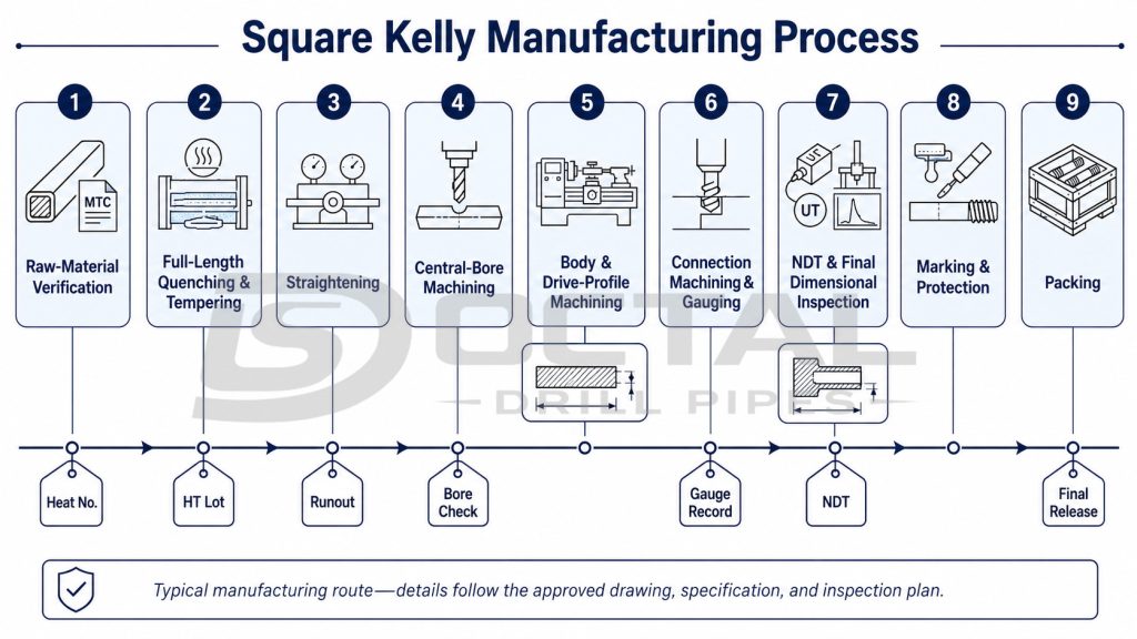
Square Kelly Manufacturing Process
Raw-material verification → full-length quenching and tempering → straightening → central-bore machining → body and drive-profile machining → connection machining and gauging → NDT and final dimensional inspection → marking, protection and packing.
Critical Dimensional Control During Kelly Manufacturing
The kelly must remain straight, internally centered and dimensionally compatible with the matching kelly bushing. These conditions are controlled throughout production because heat treatment, deep-hole boring and heavy external machining can each release residual stress and change the final geometry.
Straightness and Runout Control
Straightness is checked after heat treatment, initial straightening, bore machining, drive-profile milling and connection machining. The kelly is supported at controlled points and rotated or referenced along its length while runout is measured at the drive section, transition areas and connection ends.
Intermediate inspection allows local bowing or machining distortion to be corrected before the next operation. A bent drive section may bind inside the kelly bushing, concentrate torque on one flat or corner, and accelerate uneven wear.
Bore Alignment and Remaining Wall Thickness
The central bore is checked together with the external drive profile rather than as an isolated diameter. Bore diameter and position are verified at the ends and at defined locations along the body to confirm that the fluid passage remains aligned with the product centerline.
Wall thickness is also reviewed at several clock positions. This confirms that bore eccentricity has not reduced the remaining section below the approved drawing requirement, particularly at the drive corners, transition zones and connection ends.
Drive-Profile Geometry and Bushing Compatibility
The square or hexagonal drive section is inspected during milling and again after final machining. Measurements normally cover:
- across-flats and across-corners dimensions;
- drive-section length;
- local straightness and overall twist;
- flat-to-flat symmetry;
- corner radius and transition profile; and
- alignment between the drive body, bore and connection ends.
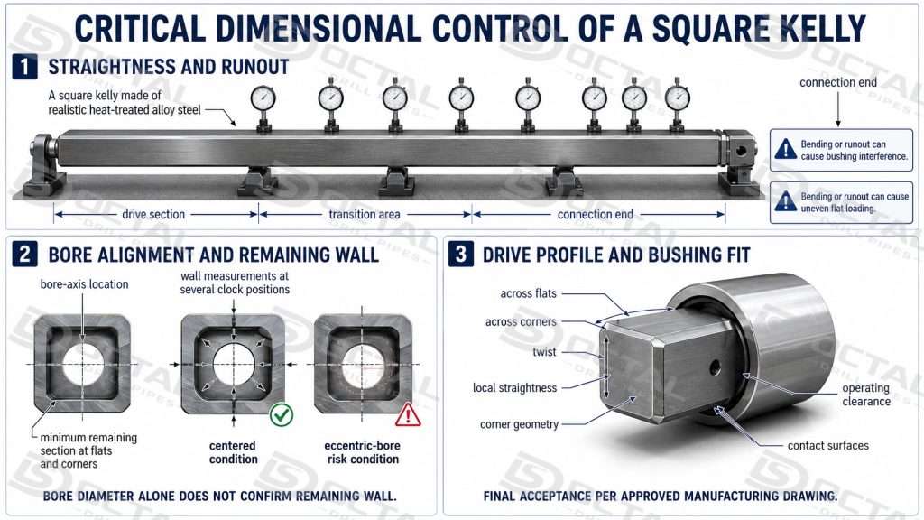
These checks confirm that the kelly can enter the specified bushing, retain the required operating clearance and transmit torque through the intended drive surfaces. Final acceptance should be based on the approved manufacturing drawing, dimensional report and applicable purchase requirements.
Inspection and Quality-Control Plan
| Inspection or Record | How It Is Checked | What It Confirms | Risk Controlled |
|---|---|---|---|
| Material certificate | Match the marked heat number to the MTC; review grade, chemical composition and delivery condition. | Correct alloy-steel heat and traceability | Material substitution or mixed heats |
| Heat-treatment record | Verify furnace batch, quenching and tempering cycles, lot identity and linked test records. | Full-length heat-treatment route | Uneven or unverified properties |
| Tensile test | Machine a specimen from the specified test location and record yield strength, tensile strength and elongation. | Required strength and ductility | Under-strength or low-ductility material |
| Charpy impact test | Notched specimens are conditioned at the specified temperature and broken in a pendulum impact machine; individual and average absorbed-energy values are recorded. | Impact toughness at the stated test condition | Brittle response under shock or low temperature |
| Hardness test | Take Brinell or approved equivalent readings at defined locations on the drive body and end sections. | Heat-treatment consistency across the product | Excessive hardness, soft zones or uneven treatment |
| Ultrasonic testing | Calibrate the UT unit against an approved reference standard and scan the specified body and end zones for internal indications. | Internal soundness of the bar and machined product | Cracks, inclusions or subsurface discontinuities |
| Magnetic-particle inspection | Magnetize the specified flats, corners, transitions and connection areas, then apply visible or fluorescent particles. | Surface and near-surface condition | Cracks at highly stressed machined areas |
| Straightness inspection | Support the kelly at controlled points and measure full-length and local runout with a calibrated indicator or equivalent setup. | Free travel through the matching bushing | Binding, uneven contact and concentrated wear |
| Drive-profile inspection | Measure across-flats, across-corners, drive length, twist and corner geometry with calibrated tools or profile gauges. | Compatibility with the specified kelly bushing | Excessive clearance, interference or uneven torque transfer |
| Bore and wall inspection | Check bore diameter and alignment, then verify remaining wall thickness at several circumferential positions. | Continuous fluid passage and adequate section thickness | Restricted bore, eccentricity or locally thin wall |
| Connection inspection | Match each end to the approved drawing, gauge the applicable rotary shouldered thread and inspect the shoulder and bore transition. | Correct upper and lower connection configuration | Wrong thread hand, poor shoulder contact or incompatible mating component |
| Final visual and release inspection | Review finished surfaces, permanent marking, connection protectors and the completed inspection dossier before packing. | Product identity and shipment readiness | Handling damage, corrosion or lost traceability |
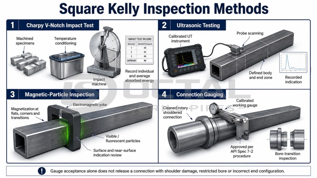
Charpy test temperature, specimen size, orientation, sampling location and acceptance values must be stated in the purchase specification or approved ITP. UT and MPI coverage should follow the applicable specification, manufacturing procedure and project inspection plan rather than being described as universal 100% coverage.
Square Kelly Applications and Selection Requirements
Rotary-Table Drilling Systems
A square kelly is used where the rotary table, master bushing and kelly bushing form the primary torque-transmission system. During drilling, the drive section rotates inside the matching bushing while moving vertically as the bit advances.
Selection should confirm the drive profile, across-flats dimensions, overall length, effective travel length and operating clearance with the installed kelly bushing. The upper and lower connections must also match the swivel, saver sub and drill-pipe string.
Replacement for an Existing Kelly
A replacement kelly should be matched to the previous approved drawing or verified measurements from the existing rig equipment. Nominal drive size alone is not sufficient because two kellys with the same stated size may differ in bore, drive length, connection hand, pin or box arrangement, upset geometry and bushing clearance.
The replacement review should therefore cover the complete operating interface rather than only the external square dimension.
Land, Workover and Backup Rotary Systems
Square kellys remain applicable on land rigs, workover rigs and older rotary systems that use a kelly as the main drive component. Some top-drive rigs may also retain a rotary table and kelly equipment for backup or specific handling operations.
Where the top drive supplies normal drilling torque directly to the drill string, the kelly is not the primary driving component. The rig equipment list and operating procedure should therefore be checked before including a square kelly in the drill-string configuration.
Square Kelly Specification and Acceptance Summary
| Item | Typical Product Requirement |
| Product category | Rotary drill stem element |
| Drive configuration | Square or hexagonal |
| Common material route | AISI 4145H Modified alloy steel |
| Heat treatment | Full-length quenching and tempering |
| Primary operation | Rotary-table torque transmission |
| Secondary functions | Vertical movement and drilling-fluid circulation |
| Product standard | API Spec 7-1, current applicable edition |
| Connection control | API Spec 7-2 threading and gauging |
| Typical upper end | Left-hand box connection |
| Typical lower end | Right-hand pin connection |
| Critical dimensional controls | Straightness, drive profile, bore position, upset dimensions and connection geometry |
| Main release documents | MTC, mechanical-test report, NDT report, dimensional report and connection-gauge record |
FAQ
Q1:Is a square kelly the same as drill pipe?
A1:No. A square kelly is an API Spec 7-1 rotary drill stem drive element with a square external profile. Conventional steel drill pipe is an API Spec 5DP tubular product with a round pipe body and welded tool joints.
Q2:How does a square kelly transmit torque?
A2:The rotary table turns the kelly bushing. The bushing contacts the square drive flats and transfers torque into the kelly, which then rotates the saver sub, drill pipe and bit.
Q3:Why is the upper kelly connection usually left-hand?
A3:The upper connection arrangement is designed for compatibility with the swivel-side equipment and the operating rotation of the assembly. The exact connection and hand must still be stated on the drawing and purchase order.
Q4:Which dimensions must match the kelly bushing?
A4:The drive profile, across-flats dimension, across-corners geometry, operating clearance, drive length and straightness must be compatible with the bushing.
Q5:Is a 40-ft square kelly suitable for every rig?
A5:No. Forty feet is a common published overall length, but the required kelly length depends on rig-floor geometry, available travel, handling arrangement and the installed rotary system.


