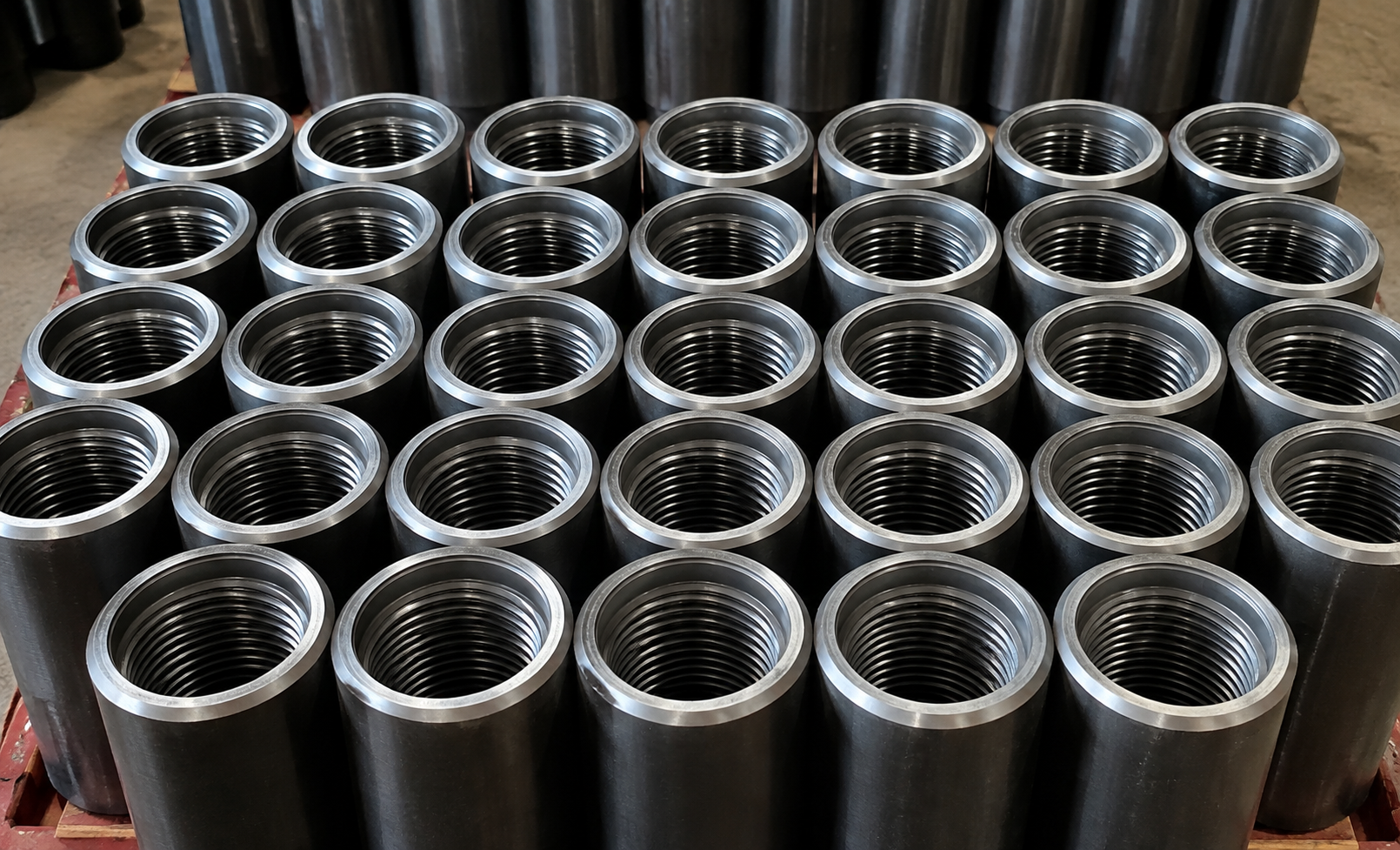
Drill pipe crossover subs connect drill pipe to HWDP, drill collars or BHA tools when the adjoining drill-string components use different rotary connections. Each end is machined for the specified mating connection, allowing a change in connection type, size or pin/box arrangement without replacing the surrounding drill-string components. The crossover body also maintains the required internal bore so drilling fluid can pass through the connection transition.
A drill string crossover sub is therefore selected from the interfaces at both ends rather than from OD alone. The upper connection, lower connection, pin/box orientation, connection designation, bore and overall length must correspond to the actual drill-string arrangement. This is most often encountered at drill-string transition points, such as drill pipe to HWDP, HWDP to drill collar, or drill pipe to a specified BHA tool. In practical drilling service, a crossover sub is used to connect components with different rotary connections while keeping the planned drill-string assembly, load path and internal fluid passage unchanged.
Drill Pipe Crossover Sub Types and Connection Configurations
The basic configuration of a crossover sub describes whether each end terminates in a male pin or female box connection. Three arrangements cover the common connection orientations used for drill-string crossover subs.
| Configuration | End Arrangement | Connection Requirement |
|---|---|---|
| Box × Pin | Box on one end and pin on the opposite end | The specified box and pin connections must match the two mating components |
| Box × Box | Box connections at both ends | Used where both adjoining components present compatible pin ends |
| Pin × Pin | Pin connections at both ends | Used where both adjoining components present compatible box ends |
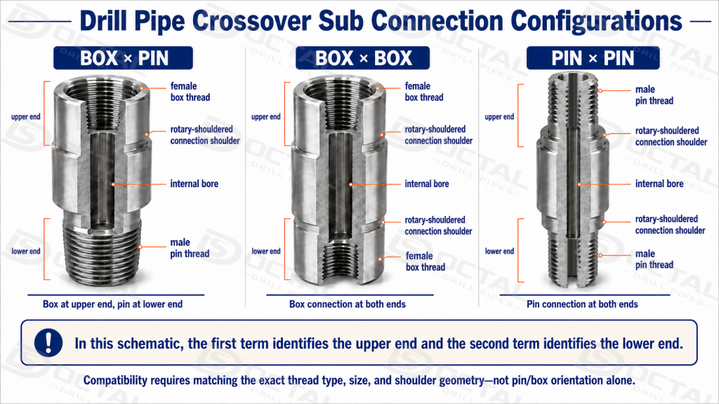
Box × Pin, Box × Box and Pin × Pin describe only the connection orientation at the two ends of the crossover sub. Actual compatibility depends on the specified connection designation, thread geometry, shoulder interface and size at each end. A crossover with the correct pin/box arrangement can still be unsuitable if either connection does not match the adjoining drill-string component.
The crossover must therefore be defined from the actual components being joined. When connecting drill pipe to HWDP, drill collars or a BHA tool, the upper and lower connections are confirmed first, followed by the required OD, internal bore and overall length. This ensures that the sub fits the planned drill-string assembly while maintaining the required mechanical connection and drilling-fluid passage.
Connection Compatibility and Sizing
Connection compatibility starts with the two components that the crossover sub must join. The upper and lower ends must match the specified connection type, size and pin/box orientation; OD alone cannot confirm whether the components can be made up correctly. Shoulder geometry must provide the required contact after make-up, while the bore and overall length must fit the surrounding drill pipe, HWDP, drill collar or BHA arrangement. The following items should be confirmed before the crossover sub is selected or machined.
| Selection Item | What Must Be Confirmed |
|---|---|
| Upper Connection | Exact connection required by the component above the crossover |
| Lower Connection | Exact connection required by the component below the crossover |
| Pin / Box Orientation | Required male or female arrangement at each end |
| Connection Type / Size | Actual mating rotary connection designation |
| Shoulder Interface | Correct shoulder contact after make-up |
| OD | External dimensional fit with adjacent drill-string components |
| ID / Bore | Internal clearance and drilling-fluid passage |
| Overall Length | Required crossover length in the assembled string |
| Mating Component | Drill pipe, HWDP, drill collar or BHA tool connected at each end |
A rotary shouldered connection relies on both the threaded section and the mating shoulders to achieve correct make-up and transfer drilling loads. For a crossover sub, compatibility therefore depends on the complete connection geometry—not simply on whether one end is a pin and the other is a box. The specified connection type, size, thread geometry and shoulder interface must match the component connected at each end.
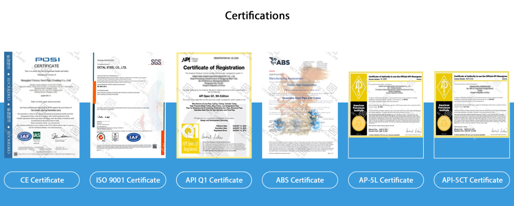
API Spec 7-1 and API Spec 7-2 control different parts of the crossover-sub connection. API 7-1 covers applicable product requirements for drill stem subs and related rotary drill stem elements, while API 7-2 controls the dimensions, threading, gauging and inspection of standardized rotary shouldered connections. For a drill pipe crossover sub, the component requirements and the connection requirements therefore need to be checked separately.
| Reference | Relevance to Drill Pipe Crossover Subs |
|---|---|
| API Spec 7-1 — Rotary Drill Stem Elements | Covers applicable requirements for drill stem subs and related rotary drill stem elements |
| API Spec 7-2 — Threading and Gauging of Rotary Shouldered Connections | Controls dimensions, threading, gauging and inspection of standardized rotary shouldered connections |
API compliance alone does not confirm that a crossover sub will fit the intended drill string. The exact upper and lower connection designations must match the mating drill pipe, HWDP, drill collar or BHA tool, and the crossover OD, bore and overall length must suit the planned assembly. Connection compatibility should therefore be confirmed from the actual components on both sides of the crossover before the sub is manufactured or selected.
Where Drill Pipe Crossover Subs Are Used
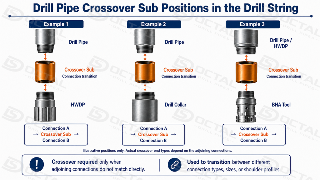
A drill pipe crossover sub is installed at a drill-string transition where the component above and the component below must remain in the same assembly but their rotary connections do not match directly. The mismatch may involve the connection family, nominal connection size, pin/box arrangement or the connection presented by a lower BHA tool. The crossover provides the required threaded transition while maintaining the planned drill-string OD, internal bore and fluid passage.
In practice, the need for a crossover is determined at the interface between two actual components. A drill pipe and an HWDP may connect directly when they use compatible connections; if the connection designation changes, a crossover is introduced. The same logic applies when the main drill-pipe string is connected to drill collars or a BHA tool. Crossover sub selection is therefore based on the exact upper and lower connections being joined, together with the required OD and internal bore, rather than on one nominal diameter alone.
| Drill-String Interface | When a Crossover Sub Is Required | What Must Be Matched |
|---|---|---|
| Drill Pipe ↔ Drill Pipe | Used when two drill-pipe sections or tool joints have different specified rotary connections and cannot be made up directly | Connection designation at both ends, pin/box orientation, OD, bore |
| Drill Pipe ↔ HWDP | Used when the drill-pipe connection differs from the connection specified on the heavy weight drill pipe | Drill-pipe connection, HWDP connection, bore continuity and external clearance |
| Drill Pipe ↔ Drill Collar | Provides the transition from the main drill-pipe string to the lower drill-collar section when the two components use different connection sizes or types | Upper drill-pipe connection, lower drill-collar connection, shoulder interface, OD and bore |
| Drill Pipe ↔ BHA Tool | Used when a downhole tool in the BHA presents a different connection from the drill pipe or intermediate drill-string component | Tool connection, drill-pipe-side connection, pin/box arrangement, bore and assembly length |
| Drill Collar ↔ Drill Collar / BHA Tool | Used within the lower drill string when adjoining drill collars or BHA components have different connections | Both lower-string connections, shoulder geometry, OD and internal passage |
The drill pipe to drill collar crossover sub is a common connection-transition configuration between the main drill-pipe section and the heavier, stiffer lower assembly. It is required when the drill pipe and drill collar use different rotary connection sizes, types or end configurations. The crossover is machined with the specified connection at each end while maintaining the required OD and internal bore for the assembled drill string.
Crossover subs are also used during BHA make-up and tool changes when a replacement or additional downhole component has a connection that does not directly match the adjoining drill-string element. In these positions, the crossover provides the required mechanical connection while maintaining the drilling-fluid passage through the assembled string.
Materials and Heat Treatment
Integral oilfield crossover subs commonly use heat-treated alloy steel because the short body contains two threaded ends, shoulder sections and an internal bore while transmitting torque and axial load between drill-string components.
4145H modified alloy steel is commonly used for integral rotary subs because it can be heat treated to provide the strength and toughness required at threaded ends, shoulders and reduced cross-sections. 4140-series alloy steels may also be specified depending on the connection design, component dimensions and required mechanical properties. The final material grade and heat-treatment condition should therefore be matched to the crossover-sub design rather than treated as one fixed material requirement.
| Material / Condition | Engineering Role |
|---|---|
| 4145H Modified Alloy Steel | Common material route for integral oilfield drill-string subs |
| 4140-Series Alloy Steel | Used for some crossover and rotary-sub designs according to product requirements |
| Quenched and Tempered Condition | Develops the specified combination of strength and toughness in heat-treatable alloy steel |
Material selection cannot be separated from the connection and component geometry. A 4145H crossover sub is not defined by the material designation alone; the finished part still requires the correct connection machining, bore, OD, overall length and heat-treatment condition for the specified design.
The threaded ends and shoulders deserve particular attention because these areas transfer load through repeated make-up and break-out cycles. Material condition, machining quality and connection geometry must therefore be controlled as a combined system rather than treated as independent specifications.
Manufacturing of Integral Drill Pipe Crossover Subs
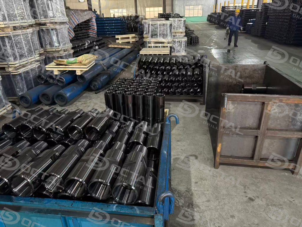
Integral drill pipe crossover subs are manufactured from alloy-steel stock or bar selected for the specified connection design, finished dimensions and mechanical-property requirements. The body, internal bore and two end connections are produced as one integral component, with each connection machined to match the drill-string component installed above or below the crossover.
The exact production sequence can vary with material condition and product design, but the main controlled operations normally include:
- Material identification and blank preparation – verifies the specified alloy steel and maintains material traceability before machining.
- Heat treatment – develops the required mechanical properties for the crossover body, threaded ends and shoulder sections.
- OD and body machining – establishes the finished outside profile and the dimensional relationship between the two ends.
- Internal bore machining – produces the required internal passage and maintains alignment through the crossover.
- Upper and lower connection machining – forms the specified pin or box connection independently at each end.
- Thread and shoulder finishing – controls the thread profile and shoulder surfaces required for correct make-up with the mating components.
- Connection gauging and dimensional verification – confirms the specified connection geometry, OD, bore and overall length.
- Specified NDT, where required – verifies the applicable product areas according to the drawing, specification or purchase requirement.
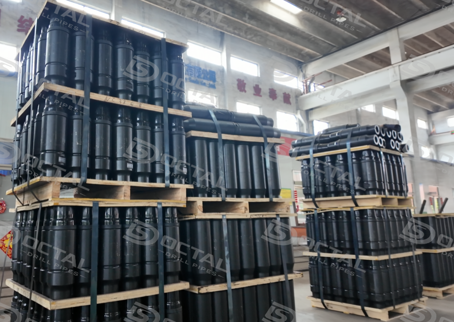
- Marking and thread protection – identifies the finished component and protects machined connections during storage and transport.
The finished crossover sub is verified as a complete component, with particular attention to the upper and lower connections, thread and shoulder geometry, OD, internal bore and overall length. Where standardized rotary shouldered connections are specified, the applicable threading and gauging requirements are followed at each end to confirm correct mating geometry. Additional NDT, thread-surface treatment and connection protection are applied where required by the product specification or service condition.
How to Select a Drill Pipe Crossover Sub
Selecting a drill pipe crossover sub begins with the two components that cannot be connected directly. The connection on the rig-side component defines one end of the crossover, while the connection on the bit-side component defines the opposite end. Only after these two mating connections are confirmed should the crossover OD, bore, length and material condition be finalized.
The selection process can be organized into five steps:
| Selection Step | What to Confirm | Selection Result |
|---|---|---|
| 1. Identify the two mating components | Component on the rig side and component on the bit side: drill pipe, HWDP, drill collar or BHA tool | Defines where the crossover will be installed |
| 2. Confirm both connection designations | Exact connection type and size on each mating component | Defines the upper and lower crossover connections |
| 3. Determine pin / box configuration | Whether each mating component presents a pin or box end | Determines Box × Pin, Box × Box or Pin × Pin configuration |
| 4. Match the crossover dimensions | OD, internal bore and required overall length | Ensures the crossover fits the drill-string geometry and maintains the required fluid passage |
| 5. Confirm material and service condition | Alloy-steel grade, heat-treatment condition and any service-specific requirements | Defines the finished crossover construction and material condition |
Start with the two connections
The most important information is the exact connection designation on each side. A crossover cannot be selected correctly from drill pipe OD or a description such as “Box × Pin” alone. Box and pin identify only the end orientation; they do not define the thread size or connection geometry.
The connection data should therefore be established as:
Rig-Side Component → Required Crossover Connection → Crossover Body → Required Crossover Connection → Bit-Side Component
For a standardized rotary shouldered connection, the specified connection designation should correspond to the applicable dimensional and gauging requirements rather than being inferred from visual appearance.
Then check OD, bore and length
Once both connections are fixed, the crossover body dimensions are selected around the planned drill-string assembly.
- OD must be compatible with the adjoining drill-string components and the required external profile.
- Internal bore must provide the specified internal clearance and drilling-fluid passage.
- Overall length must fit the required string configuration without changing the intended position of the adjoining components.
These dimensions should be checked together. A crossover with the correct threads can still be unsuitable if its bore, OD or overall length does not fit the intended drill-string configuration.
Final selection
A complete crossover-sub specification should therefore identify both mating components, both connection designations, pin/box arrangement, OD, bore and overall length, followed by the required material and heat-treatment condition. The connection pair defines whether the sub can be made up correctly; the body dimensions and material then determine whether it fits the intended drill-string configuration and service condition.
FAQ
Q1: Can any Box × Pin crossover sub connect two Box-to-Pin drill-string components?
A1: No. Box × Pin defines only the end orientation. The exact connection type and size at both ends, together with the shoulder geometry and bore, must match the mating drill-string components.
Q2: When is a crossover sub required between drill pipe and drill collar?
A2: A crossover sub is required when the drill pipe and drill collar cannot make up directly because their connection types, sizes or end configurations differ. If the two components already have compatible connections, an additional crossover is not required.
Q3: Does API 7-1 compliance mean a crossover sub will fit any API drill pipe connection?
A3: No. API Spec 7-1 covers applicable drill stem subs, while rotary shouldered connection threading and gauging are addressed separately by API Spec 7-2. The exact connection designation at each end must still match the mating component.
Q4: Is 4145H material alone enough to specify a drill pipe crossover sub?
A4: No. Material grade alone does not define the finished crossover. The upper and lower connections, pin/box arrangement, OD, bore, overall length and heat-treatment condition must also match the intended drill-string configuration.