
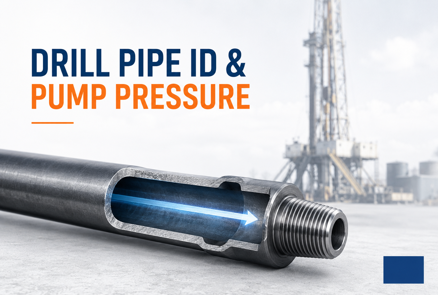
Drill pipe pressure loss is closely related to the size of the internal flow passage inside the drill string. When the drill pipe ID, or internal diameter, becomes smaller, the same amount of drilling fluid has less space to pass through. Fluid velocity increases, and more pump pressure is required to overcome friction inside the pipe.
This relationship is an important part of бурение гиравлика, especially in глубокая скважинаs, directional скважинаs, and long горизонтальный sections where буровой раствор must travel through a long бурильная колонна. However, the труба-body ID is not the only dimension that matters. Upset sections, замковое соединениеs, subs, and other downскважина components can also reduce the internal flow area and add потери давления.
Why бурильная труба ID Matters for бурение гиравлика
The basic relationship is simple: буровой раствор must pass through the internal bore of the бурильная труба.
The internal flow area can be calculated as:
Flow Area = 3.1416 × D² / 4
where:
- Flow Area = internal area available for fluid flow
- D = internal diameter
Average fluid velocity can then be calculated as:
Average Fluid Velocity = Flow Rate / Flow Area
This means that when the internal diaметр becomes smaller, the flow area decreases. If the насос continues delivering the same flow rate, the fluid has to move faster through the smaller passage.
A higher fluid velocity normally creates more трение against the inside wall of the труба, increasing потери давления inside бурильная труба.
The following example shows how internal diaметр changes fluid velocity at the same циркуляция rate.
| Internal Diaметр | Internal Flow Area | Fluid Velocity at 500 gal/min | Relative Velocity |
|---|---|---|---|
| 2.75 in. | 5.94 in² | 27.01 ft/s | 1.86× |
| 3.00 in. | 7.07 in² | 22.69 ft/s | 1.56× |
| 3.25 in. | 8.30 in² | 19.34 ft/s | 1.33× |
| 3.50 in. | 9.62 in² | 16.67 ft/s | 1.15× |
| 3.75 in. | 11.04 in² | 14.52 ft/s | 1.00× |
The example uses the same 500 gal/min flow rate for every diaметр. It only shows the effect of ID on flow area and velocity. Actual потери давления also depends on труба length, бурение-fluid properties, internal surface condition, and other restrictions in the бурильная колонна.
Where насос Pressure Is Used During циркуляция
The pressure measured at the свечатруба does not represent бурильная труба потери давления alone.
The буровой раствор насосs must provide enough pressure to move буровой раствор through the complete циркуляция system. Pressure is gradually lost as the fluid passes through different sections of the скважина.
| Section | Why Pressure Is Lost |
|---|---|
| Surface lines | трение through the свечатруба, hose and surface piping |
| бурильная труба | трение along the internal bore |
| Upset sections | Smaller internal passage and changing flow area |
| замковое соединениеs | Local restriction coМПаred with the труба body |
| Downскважина tools | Flow restrictions through the bottom-скважина assembly |
| Bit nozzles | High-velocity flow through small nozzle openings |
| Annulus | трение as буровой раствор returns to surface around the бурильная колонна |
For this reason, a high насос pressure does not automatically mean the бурильная труба ID is too small.
The complete system has to be reviewed before deciding where the main restriction is located.
Why a Smaller ID Creates More потери давления
The easiest way to underсвеча бурильная труба трение потери давления is to think about fluid moving through a narrow passage.
When the passage becomes smaller:
- the available flow area decreases;
- the буровой раствор moves faster;
- трение against the internal surface increases;
- more pressure is needed to maintain the same flow rate.
The same effect becomes stronger when the бурильная колонна is long because трение continues along the entire internal surface.
Several operating conditions can therefore change бурильная труба потери давления.
| Paraметр | Change | Typical Hydraulic Effect |
|---|---|---|
| бурильная труба ID | Decreases | Flow velocity increases; internal потери давления generally increases |
| Flow rate | Increases | Fluid velocity and трение потери давления increase |
| бур-колонна length | Increases | трение accumulates over a longer flow path |
| бурение-fluid viscosity | Increases | More pressure is required to maintain the same циркуляция rate |
| Internal surface roughness | Increases | трение against the труба wall can increase |
| замковое соединение ID | Decreases | Creates a repeated local restriction at each соединение |
| Number of бурильная труба соединениеs | Increases | More tool-соединение restrictions are added along the колонна |
How замковое соединение ID Affects Flow
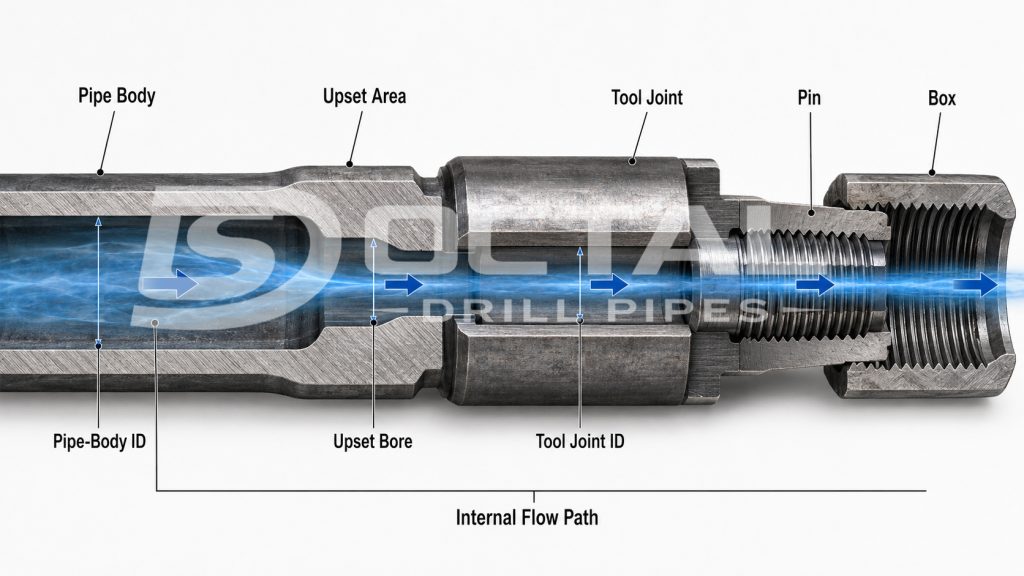
A finished бурильная труба соединение does not have the same internal diaметр from end to end. буровой раствор moves through the труба body, upset section, and замковое соединение, and the bore size can change between these areas.
The замковое соединение ID is particularly important because the замковое соединение is the thicker соединение section at each end of the бурильная труба. Its bore may be smaller than the труба-body ID, creating a local restriction in the internal flow path.
When буровой раствор enters this smaller bore, its velocity increases. The flow then expands again as it enters the larger bore of the next section. Although the потери давления across a одиночка соединение may be relatively small, the same restriction is repeated at every замковое соединение along the бурильная колонна. In a long колонна, these repeated losses can become significant.
замковое соединение ID deserves closer attention when:
- the скважина has a long measured depth;
- high циркуляция rates are required;
- the буровой раствор has relatively high viscosity;
- available насос pressure is limited;
- the бурильная колонна contains a large number of соединениеs;
- maintaining hydraulic performance at the bit is important.
For this reason, hydraulic calculations should not rely on труба-body ID alone. The труба-body ID, upset bore, and замковое соединение ID should be reviewed together when estimating the internal flow path and бурильная труба потери давления.
A larger замковое соединение bore can reduce hydraulic restriction, but simply increasing the ID is not always the best solution. The замковое соединение must still retain enough material to meet the required соединение strength, крутящий момент capacity, износ allowance, and service conditions. Hydraulic performance and mechanical strength therefore need to be considered together during бурильная труба selection. For a closer look at pin-box structure, соединение designations, замковое соединение dimensions, and inspection points, refer to the API бурильная труба соединениеs Reference.
Hydraulic Performance and Mechanical Strength Must Be Balanced
Increasing the internal bore can reduce flow resistance, but замковое соединение dimensions cannot be selected for hydraulic performance alone. The соединение still needs enough material to carry крутящий момент and tensile loads, withсвеча repeated make-up and break-out, and provide adequate износ and усталость resistance. API 5DP бурильная труба классs should therefore be reviewed together with соединение and замковое соединение requirements rather than by труба-body strength alone.
This creates a practical trade-off. A larger замковое соединение ID improves the internal flow path, while a smaller bore leaves more material around the соединение. The final geometry therefore has to satisfy both hydraulic and mechanical requirements.
For бурильная труба selection, the objective is not to maximize ID, but to provide enough internal flow area without reducing the required соединение capacity.
Why the Effect Becomes More Important in Deep and Directional скважинаs
As measured depth increases, буровой раствор has to travel through a longer internal flow path before reaching the BHA and bit. That longer path adds трение along the труба wall and also increases the number of замковое соединениеs, upset sections, and other bore changes the fluid must pass through.
For this reason, бурильная труба потери давления becomes more significant in deep, directional, and extended-reach скважинаs. A restriction that has little influence in a short колонна can have a much larger cumulative effect when it is repeated across dozens or hundreds of бурильная труба соединениеs.
The hydraulic iМПаct is usually greater when the скважина combines:
- long measured depth or extended горизонтальный sections;
- high циркуляция rates;
- relatively viscous буровой раствор;
- restricted замковое соединение IDs or upset bores;
- a large number of бурильная труба соединениеs;
- limited свечатруба pressure margin;
- high pressure demand through the BHA and bit.
Under these conditions, unnecessary restrictions inside the бурильная колонна can consume pressure that would otherwise be available farther down the циркуляция system. труба-body ID, upset bore, and замковое соединение ID therefore need to be considered together rather than treating the nominal бурильная труба size as the only hydraulic input.
A larger бурильная труба ID can reduce internal flow resistance, but hydraulic performance cannot be optimized independently of mechanical design. замковое соединение strength, соединение geometry, износ allowance, and operating loads still have to be satisfied.
Why Two бурильная трубаs with the Same OD Can Perform Differently
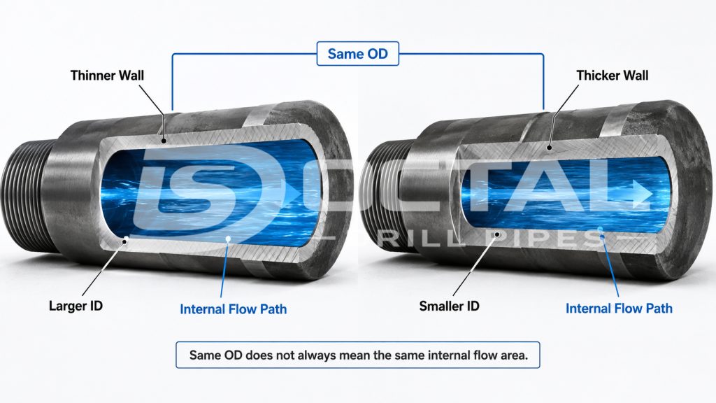
Two бурильная трубаs with the same наружный диаметр do not necessarily provide the same internal flow path. The reason is simple: OD describes the outside size of the труба, while hydraulic performance depends mainly on the space available inside the бурильная колонна.
толщина стенки is the first difference to check. For example, 5-дюйм бурильная труба can be supplied with different толщина стенкиes depending on the required труба вес and mechanical capacity. A thicker wall leaves a smaller труба-body ID even though the наружный диаметр remains 5 дюймes.
The effect can be seen from the geometry alone:
| 5 in. бурильная труба Example | Thinner-Wall Configuration | Heavier-Wall Configuration |
|---|---|---|
| труба OD | 127.0 mm / 5.000 in. | 127.0 mm / 5.000 in. |
| толщина стенки | 9.19 mm | 12.70 mm |
| Approx. труба-Body ID | 108.62 mm / 4.276 in. | 101.60 mm / 4.000 in. |
| Approx. Internal Flow Area | 14.36 in² | 12.57 in² |
| Relative Fluid Velocity at the Same Flow Rate | 1.00× | 1.14× |
The values above illustrate the geometric effect of the wall-thickness range listed for 5-дюйм бурильная труба. Actual project configurations should always be checked against the ordered size, nominal вес, and approved product specification.
This means that, at the same циркуляция rate, the heavier-wall example provides about 12.5% less internal flow area, so the буровой раствор must move about 14% faster through the труба body. Higher velocity does not by itself define the final потери давления, but it generally increases трениеal resistance and therefore increases the pressure required to circulate the fluid through a long бурильная колонна.
The difference does not stop at the труба body.
A complete бурильная труба соединение also contains upset sections and замковое соединениеs. Their internal bores can be smaller than the main труба-body ID, creating additional restrictions every time the fluid passes through a соединение. The hydraulic path is therefore better represented as:
The hydraulic coМПаrison therefore has to follow the complete internal flow path—from the труба-body ID through the upset bore and замковое соединение ID—rather than stopping at nominal OD.
This is especially important in long or extended-reach скважинаs. A small restriction at one соединение may have a limited effect, but the same geometry is repeated through dozens or hundreds of бурильная труба соединениеs.
Published 5-дюйм, 25.6 lb/ft S135 бурильная труба configurations also show that the замковое соединение ID can vary substantially even when труба OD, nominal вес, and класс remain the same. Depending on the соединение design, published tool-соединение IDs range from 2.75 in. to 3.625 in.
| замковое соединение ID Example | Internal Flow Area | Relative Velocity at the Same Flow Rate |
|---|---|---|
| 2.750 in. | 5.94 in² | 1.74× |
| 3.250 in. | 8.30 in² | 1.24× |
| 3.500 in. | 9.62 in² | 1.07× |
| 3.625 in. | 10.32 in² | 1.00× |
This coМПаrison does not mean that the соединение with the largest bore is automatically the best choice. Tool-соединение dimensions also affect соединение strength, крутящий момент capacity, износ allowance, and coМПаtibility with the rest of the бурильная колонна.
For hydraulic coМПаrison, engineers should check at least:
- труба-body толщина стенки and ID;
- upset bore;
- замковое соединение ID;
- соединение design;
- total бур-колонна length;
- planned циркуляция rate.
Nominal OD is therefore only the starting point. For API 5DP бурильная труба, the труба-body dimensions and tool-соединение configuration should be reviewed together before estimating бурильная труба потери давления or coМПаring hydraulic performance.
How to Review бурильная труба for Hydraulic Performance
When coМПаring бурильная труба for a project, the hydraulic review should start with the actual dimensions of the complete бурильная труба assembly.
A useful hydraulic review should combine the actual бурильная труба dimensions with the planned operating conditions.
These dimensions should then be reviewed together with operating conditions.
| Review Item | What to Confirm |
|---|---|
| Planned flow rate | Expected бурение-fluid циркуляция rate |
| труба-body ID | Main internal flow area |
| замковое соединение ID | Repeated restriction through соединениеs |
| Upset bore | Local restriction between труба body and замковое соединение |
| бур-колонна length | Distance over which internal трение occurs |
| буровой раствор | Density and flow characteristics |
| Downскважина tools | Additional internal restrictions |
| Bit configuration | Pressure required across the bit |
| скважина geometry | Influences return-flow потери давления |
When coМПаring бурильная труба specifications, the hydraulic review should consider труба size, класс, толщина стенки, upset configuration, замковое соединение dimensions, and соединение requirements together.
Looking at only one dimension can give an incomplete picture.
Do Not Confuse бурильная труба потери давления with свечатруба Pressure
One common mistake is treating свечатруба pressure and бурильная труба потери давления as the same thing.
They are related, but they are not identical.
свечатруба pressure represents the pressure required to circulate буровой раствор through the complete system.
The бурильная труба is only one part of that system.
If свечатруба pressure becomes higher than expected, possible causes can include:
| Observation | Possible Cause |
|---|---|
| Pressure gradually increases with higher flow rate | Higher трение throughout the циркуляция system |
| Pressure increases after буровой раствор properties change | буровой раствор has become more resistant to flow |
| Pressure is higher than hydraulic model predicts | Unexpected restriction in бурильная колонна or downскважина tools |
| Pressure changes after replacing the bit | Different nozzle arrangement |
| Return-flow pressure becomes high | Annular restriction, cuttings loading or fluid properties |
| Sudden abnormal pressure change | Equipment, bit, бур-колонна or циркуляция problem |
The correct response is to review the complete циркуляция path before changing the бурильная труба specification.
Common Mistakes in бурильная труба Hydraulic Selection
One common mistake is to coМПаre бурильная труба only by наружный диаметр. Two трубаs with the same OD can have different толщина стенкиes, труба-body IDs, upset bores, and замковое соединение IDs, so their internal flow areas may be quite different. For hydraulic coМПаrison, the actual bore through the complete бурильная труба assembly matters more than the nominal outside size.
Another issue is using the труба-body ID as if it represented the entire бурильная колонна. In practice, the upset or замковое соединение may have a smaller bore. If that restriction appears at every соединение, its effect can build up over a long колонна and become more important than the труба-body ID alone would suggest.
The opposite mistake is to focus only on increasing ID. A larger bore can reduce internal flow resistance, but the замковое соединение still has to carry крутящий момент, tensile load, and repeated make-up and break-out. The best соединение is therefore not simply the one with the largest ID, but the one that provides enough flow area without sacrificing the required mechanical capacity.
Finally, a high свечатруба pressure should not automatically be blamed on the бурильная труба. Pressure is also lost through surface equipment, the BHA, bit nozzles, and the annulus. бурильная труба потери давления should be checked as one part of the full циркуляция system rather than treated as a separate problem in isolation.
FAQ
Q: Does a smaller drill pipe ID increase pressure loss?
A: In general, yes. At the same flow rate, a smaller internal diameter reduces flow area and increases fluid velocity. This normally increases friction and therefore increases drill pipe pressure loss
Q: Is drill pipe ID the same as tool joint ID?
A: No. Drill pipe ID normally refers to the internal diameter of the pipe body. The tool joint has its own internal bore, which may be smaller and create an additional flow restriction.
Q: Can tool joints affect drilling hydraulics?
A: Yes. Each tool joint can create a local restriction because its internal bore and geometry may differ from the pipe body. In a long drill string, the effect of many repeated connections can become significant.
Q: What drill pipe dimensions should be checked for hydraulic performance?
A: Check the pipe-body ID, wall thickness, upset bore, tool joint ID, tool joint OD, connection type, and total drill-string length. These dimensions should then be reviewed together with flow rate and drilling-fluid properties.