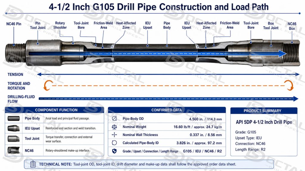
API 5DP 4-1/2 inch drill pipe is a complete load-carrying member of the drill string, assembled from a heat-treated alloy-steel pipe body, formed upset ends, and separate pin and box tool joints welded to both ends. The 4.500 in. pipe body provides the main axial-load path and drilling-fluid passage. The upset sections add material at the pipe ends for load transfer and welding, while the heavier tool joints provide the rotary shoulders, connection geometry, handling surface and wear allowance required during repeated make-up and break-out.
During drilling and tripping, the finished joint transfers rotation and torque toward the bottomhole assembly, carries tensile and bending loads, and circulates drilling fluid through the string. Unlike casing or production tubing, drill pipe is repeatedly rotated, connected, disconnected and exposed to cyclic loading. Pipe-body grade, wall thickness, upset geometry, weld integrity, tool-joint dimensions, connection condition and internal clearance must therefore be reviewed as one finished assembly.
For shipment to Oman, the approved configuration was API 5DP 4-1/2 inch G105 drill pipe with a 16.60 lb/ft nominal pipe-body weight, IEU upset ends, NC46 connections and Range 2 length. Before export packing for Sohar Port, the finished joints were reviewed for body dimensions, upset and weld transitions, tool-joint geometry, continuous internal clearance, NC46 identity and individual traceability.
Order Overview
| Item | Order Details |
|---|---|
| Destination | Sohar Port, Oman |
| Product | API 5DP 4-1/2 Inch Drill Pipe |
| Pipe-Body OD | 4.500 in. / 114.3 mm |
| Nominal Weight | 16.60 lb/ft / approximately 24.7 kg/m |
| Nominal Wall Thickness | 0.337 in. / 8.56 mm |
| Nominal Pipe-Body ID | 3.826 in. / approximately 97.2 mm |
| Grade | G105 |
| Upset Type | IEU |
| Connection | NC46 |
| Length Range | R2 |
| Release Focus | OD, weight, NC46 compatibility, drift and documents |
Industry connection references show 4.500 in. × 16.60 lb/ft pipe bodies paired with NC46-family configurations. The approved order data sheet remains the controlling reference for the actual tool-joint OD, tool-joint ID, bore and connection data used for this G105 shipment.
4-1/2 Inch G105 Drill Pipe Construction and Configuration
The designation API 5DP 4-1/2 inch drill pipe with a 114.3 mm pipe-body OD identifies the nominal outside diameter of the pipe body, but it does not define the maximum tool-joint OD, minimum internal passage or completed-joint weight. It does not define the maximum outside diameter, minimum internal passage or total weight of the complete drill-pipe joint. Those characteristics depend on the combined body, upset, tool-joint and connection design.
| Assembly Element | Ordered Configuration | Engineering Function | Release Significance |
|---|---|---|---|
| Pipe body | 4.500 in. OD, 16.60 lb/ft | Carries axial load and forms the principal drilling-fluid passage | Verify OD, wall thickness, straightness and surface condition |
| G105 grade | API high-strength drill-pipe grade | Provides the specified pipe-body strength level | Match grade marking with material and mechanical-test records |
| IEU ends | Internal-external upset | Adds section at the pipe ends for welding and load transfer | Check external profile, internal transition and remaining passage |
| Welded tool joints | Separate pin and box tool joints | Transfer torque and tensile load between adjoining joints | Review weld condition, alignment, flash removal and bore continuity |
| NC46 connection | Rotary-shouldered pin and box | Forms the repeated make-up and break-out interface | Confirm identity, thread gauging, shoulder condition and compatibility |
| Range 2 | Ordered finished-length category | Defines the required joint-length range | Confirm measured length and bundle identification |
The 16.60 lb/ft designation refers to the nominal pipe-body weight class. It is not the average shipping weight of the finished joint because the completed assembly also includes two larger tool joints and the upset sections.
The IEU upset ends on this 4-1/2 inch G105 drill pipe add material both internally and externally at the pipe ends before the separate tool joints are friction welded into the finished assembly.The increased section supports the welded tool-joint transition, but the internal upset may reduce the available passage below the calculated pipe-body ID. The tool-joint bore, upset transition and weld area must therefore remain part of the full-length drift review.
Industry connection references show 4.500 in. × 16.60 lb/ft pipe bodies paired with NC46-family configurations. The exact tool-joint OD, tool-joint ID, bore, connection dimensions and make-up data for this G105 shipment must still follow the approved order data sheet.
4-1/2 Inch Drill Pipe Dimensional and Clearance Review
The ordered 4-1/2 inch drill pipe uses a nominal pipe-body outside diameter of 4.500 in. (114.3 mm) and a nominal weight of 16.60 lb/ft (approximately 24.7 kg/m). Its nominal wall thickness is 0.337 in. (8.56 mm), producing a calculated pipe-body inside diameter of 3.826 in. (97.2 mm).
| Dimensional Item | Ordered Configuration | Inspection Significance |
|---|---|---|
| Pipe-body OD | 4.500 in. / 114.3 mm | Identifies the drill-pipe body size |
| Nominal weight | 16.60 lb/ft / 24.7 kg/m | Identifies the pipe-body weight class |
| Nominal wall thickness | 0.337 in. / 8.56 mm | Used to verify minimum remaining wall |
| Calculated body ID | 3.826 in. / 97.2 mm | Reference value for body bore and flow area |
| Length | Range 2 | Verified on the finished joint |
| Connection | NC46 | Confirmed separately on the pin and box ends |
The 16.60 lb/ft value identifies the nominal pipe-body configuration. It does not represent the total weight per foot of the completed joint after the larger tool joints have been friction welded to both ends.
Pipe-Body Size Verification
Before packing, the finished pipe body is checked for outside diameter, minimum wall thickness, straightness and overall length. OD measurements are taken at the specified positions and, where required, in more than one circumferential direction to identify local ovality or deformation.
Wall-thickness inspection focuses on the minimum measured value rather than the nominal 0.337 in. dimension alone. The report should also confirm that the pipe marking matches the measured 4.500 in. × 16.60 lb/ft configuration.
The main dimensional release points are:
- 4.500 in. pipe-body OD;
- minimum acceptable wall thickness;
- local ovality and visible deformation;
- Range 2 finished length;
- pipe-body straightness;
- absence of rejectable dents, gouges or handling damage.
Upset and Weld-Area Dimensions
The upset and friction-weld areas are reviewed separately because their geometry differs from the plain pipe body. Inspection covers the upset profile, transition length, weld alignment and bore condition through the welded section.
The transition should not create an abrupt internal step or local restriction. Tool-joint-to-pipe alignment is also checked because excessive eccentricity can reduce the available bore and introduce uneven loading during rotation.
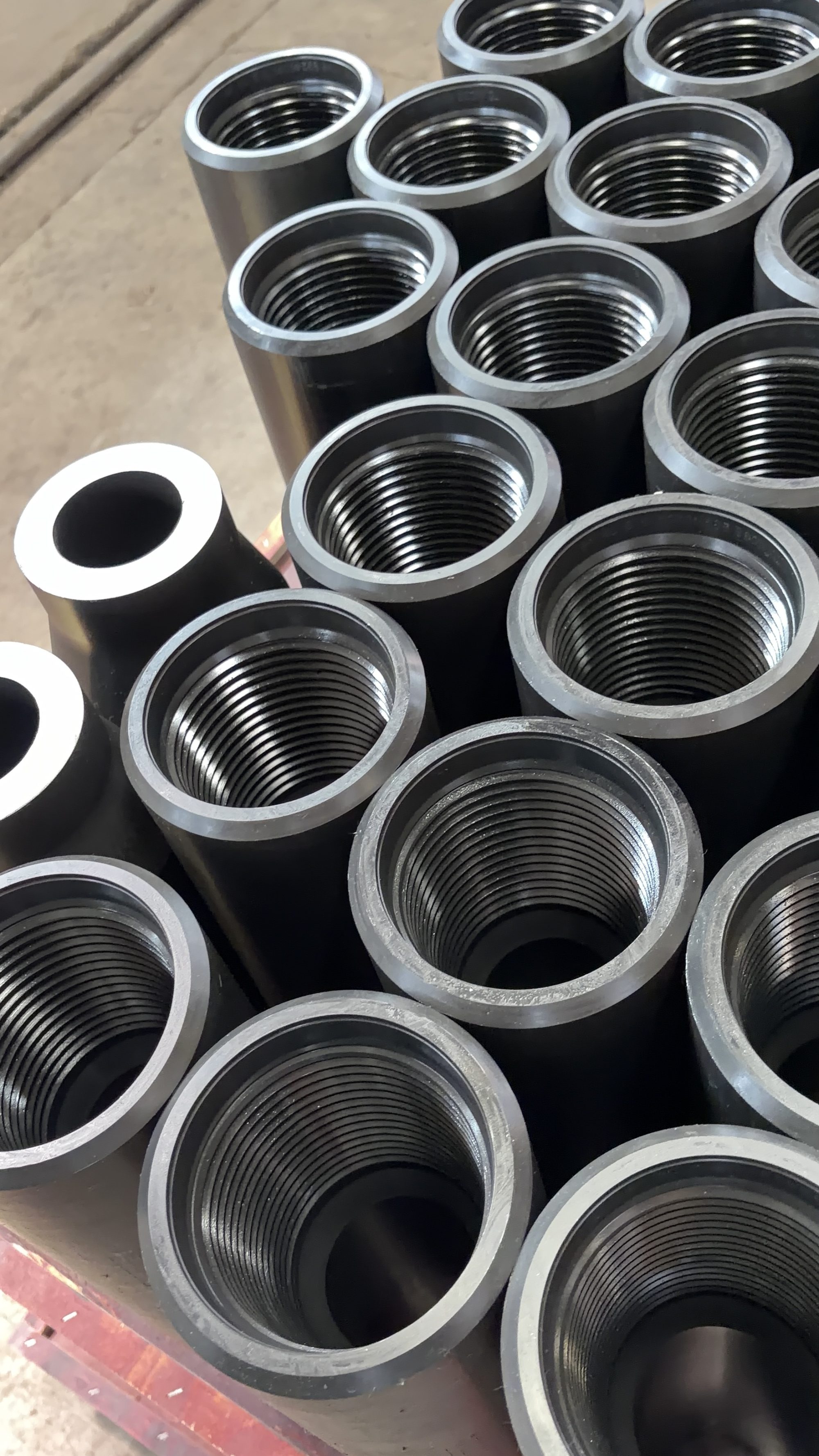
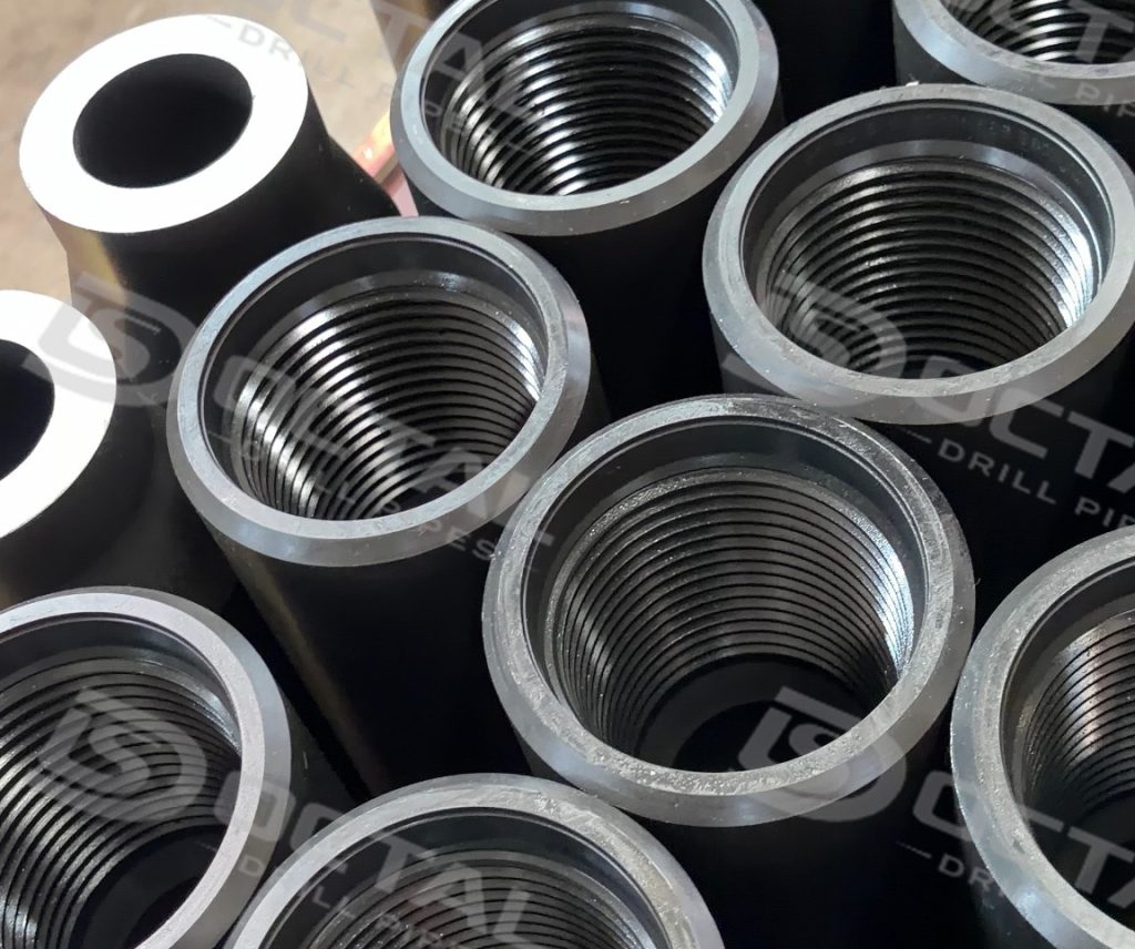
Tool-Joint OD and ID
The tool-joint dimensions are not the same as the 4.500 in. pipe-body OD and 3.826 in. body ID. The tool-joint OD is larger than the pipe body, while the tool-joint ID may be smaller than the nominal body bore.
For this reason, the finished assembly is checked for:
- pin-end and box-end tool-joint OD;
- tool-joint bore diameter;
- bore alignment through both ends;
- counterbore and internal transition;
- compatibility with the specified NC46 connection drawing.
The approved order data sheet must provide the final tool-joint OD and ID. These dimensions should not be assumed from the 4-1/2 inch pipe-body size alone.
Full-Length Drift Check
The calculated 3.826 in. body ID does not guarantee the minimum internal clearance through the complete joint. The smallest passage may occur at the upset transition, friction-weld area or tool-joint bore.
A specified drift mandrel is therefore passed through the full finished length. The test confirms that the pipe contains no internal step, weld-area obstruction or local bore restriction below the approved clearance.
The drift record should be linked to the individual pipe or traceable production lot and should show:
- specified drift size;
- full-length pass result;
- inspection status;
- reinspection result where correction was required.
Final Dimensional Release
The drill pipe is released for export packing only when the inspection records confirm the same finished configuration throughout:
4.500 in. OD × 16.60 lb/ft × 0.337 in. nominal wall × Range 2 × NC46
The final review forms part of the pre-shipment inspection for 4-1/2 inch G105 NC46 drill pipe, confirming tool-joint OD and ID, full-length drift acceptance, pipe straightness, upset and weld-area condition, and consistency between the joint marking, inspection records and packing list.This prevents a joint with the correct body diameter but an incorrect bore, connection or tool-joint configuration from reaching receiving inspection.arance should be based on the finished drill-pipe data sheet rather than the body ID alone.
4-1/2 Inch Drill Pipe Selection and Service Review
A 4-1/2 inch G105 drill pipe with 16.60 lb/ft pipe-body weight and NC46 connection may be selected when the drill-string program requires a 4.500 in. / 114.3 mm body profile, the corresponding hydraulic passage and compatibility with an NC46 connection system.The nominal size alone does not establish whether the finished joint is suitable for a particular well.
| Design Review | Practical Question | Risk Controlled |
| Outside clearance | Does the actual tool-joint OD clear the wellbore, casing and restrictions? | Contact, running interference and handling mismatch |
| Internal passage | What is the smallest continuous bore through the tool joints, upsets and pipe body? | Drift rejection, downhole-tool interference and excess pressure loss |
| Tension and torque | What combined operating load will the joint carry? | Pipe-body or connection overload |
| Bending exposure | Where will the drill pipe rotate through doglegs or high curvature? | Cyclic fatigue at the body, upset, weld and connection |
| Connection condition | Are the NC46 threads and shoulders within the approved acceptance limits? | Poor make-up, uneven shoulder contact and field rejection |
| Tool-joint wear | Has external or internal wear changed the approved geometry? | Reduced torsional capacity and altered clearance |
| Rig-floor compatibility | Do elevators, slips, tongs and protectors match the finished assembly? | Handling damage and unsafe gripping |
| Service environment | Is the material qualified for the actual corrosion or H₂S condition? | Environmental cracking and premature failure |
G105 identifies the pipe-body grade, but it does not independently establish the allowable combined load, fatigue life, connection performance or suitability for corrosive service. Final selection should use the approved body and tool-joint data together with the actual drilling program.
NC46 Connection Compatibility
The NC46 connection must match the existing drill string or approved connection plan. The release review should confirm the thread designation on the product, packing list and inspection records.
Thread-profile gauging, shoulder review and dimensional inspection should follow the contractual API 7-2 and project requirements. Exact make-up torque must come from the approved connection data rather than a generic size table.
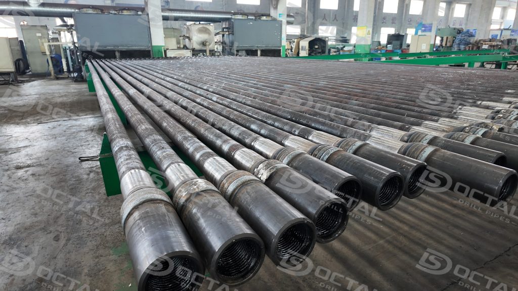
Export Packing for Sohar Port
Long drill-pipe bundles require stable support during yard handling, trucking, terminal storage and vessel loading. Pin and box ends should remain protected throughout the transport chain.
Sohar Port is an established deep-sea port and industrial logistics hub in Oman.
The shipment package should identify:
- 4-1/2 inch drill pipe size;
- G105 grade;
- 16.60 lb/ft weight class;
- NC46 connection;
- bundle number;
- heat or production-lot reference;
- packing-list position.
FAQ
Q1:What is the metric OD of 4-1/2 inch drill pipe?
A1:The nominal pipe-body OD is 114.3 mm.
Q2:Is NC46 standard on every 4-1/2 inch drill pipe?
A2:NC46 is a common option, but other configurations may be specified. Connection selection must follow the actual rig and drill-string requirement.
Q3:Why must tool-joint ID be checked separately?
A3:Because the tool-joint bore and upset transition may control the smallest internal passage, even when the nominal pipe-body ID appears sufficient.