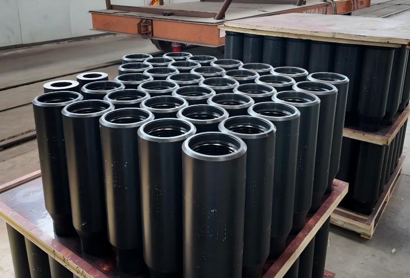
3-1/2 inch API 5DP X95 drill pipe is a welded drill-string member built from a seamless high-strength steel pipe body with externally upset ends and separate pin and box tool joints. After end upsetting and heat treatment, the pipe body is assembled with friction-welded tool joints that are finish-machined with NC38 rotary-shouldered connections. In service, the finished joint transmits rotary torque and axial load, carries drilling fluid toward the bit, and undergoes repeated bending as it rotates through vertical, deviated or curved well sections. Because the pipe body, EU transitions, weld zones, tool-joint bores, threads and shoulders form one mechanical and hydraulic path, acceptance must be based on the complete assembly rather than on the nominal body dimensions alone.
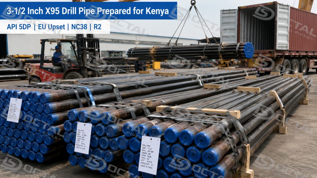
For this shipment to Kenya through the Port of Mombasa, the approved configuration included a 3.500 in. / 88.9 mm pipe-body OD, 13.30 lb/ft nominal pipe-body weight, 0.368 in. / 9.35 mm nominal wall thickness, X95 grade, EU upset ends, NC38 connections and Range 2 length. The relatively compact pipe-body profile can provide additional external clearance compared with larger drill-pipe sizes, while the smaller internal passage places greater emphasis on tool-joint bore, upset transition, weld alignment and full-length drift acceptance.
For this order, the release review was therefore based on the complete finished joint rather than the pipe-body dimensions alone. Key checks covered wall thickness, straightness, weld-area condition, NC38 thread gauging, shoulder condition and continuous internal clearance from the pin end to the box end. The joint marking, inspection records and bundle identification also had to remain consistent before export packing.
Order Overview
| Item | Order Details |
|---|---|
| Destination | Port of Mombasa, Kenya |
| Product | API 5DP 3-1/2 Inch Drill Pipe |
| Pipe-Body OD | 3.500 in. / 88.9 mm |
| Nominal Weight | 13.30 lb/ft / approximately 19.8 kg/m |
| Nominal Wall Thickness | 0.368 in. / 9.35 mm |
| Calculated Pipe-Body ID | 2.764 in. / approximately 70.2 mm |
| Grade | X95 |
| Upset Type | EU — External Upset |
| Connection | NC38 |
| Length Range | R2 |
| Release Focus | Internal clearance, connection gauging, weld area and traceability |
The calculated nominal pipe-body ID is:
3.500 in. OD − 2 × 0.368 in. wall = 2.764 in.
This value is a dimensional reference. The approved drift must still pass through the pin tool joint, upset, pipe body and box tool joint.
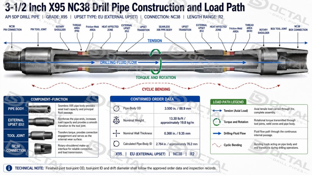
3-1/2 Inch X95 NC38 Drill Pipe Construction and Load Path
The full designation of this 3-1/2 inch API 5DP drill pipe with 88.9 mm OD and 9.35 mm nominal wall describes a connected engineering configuration rather than a single pipe dimension:
3-1/2 in. pipe-body OD → 13.30 lb/ft body weight class → 0.368 in. nominal wall → X95 grade → EU ends → welded tool joints → NC38 pin and box → Range 2 joint
Each element controls a different part of the finished drill pipe’s performance and acceptance.
| Assembly Element | Construction and Function | Order-Specific Review |
|---|---|---|
| Seamless pipe body | Forms the main load-carrying tube and drilling-fluid passage. It carries axial load, torsion, internal pressure and cyclic bending through the drill string. | Confirm 3.500 in. OD, 0.368 in. nominal wall, straightness, surface condition and calculated 2.764 in. body ID. |
| X95 pipe-body grade | API high-strength drill-pipe grade with a minimum specified yield strength of 95,000 psi. It provides a higher pipe-body yield level than E75 without defining the capacity of the entire finished joint. | Match the grade marking with the heat number, material certificate, heat-treatment lot and mechanical-test records. |
| EU upset ends | External upsetting adds metal mainly outside the original pipe-body profile to create the end section required for welding and load transfer. The actual upset bore and transition remain separate inspection points. | Examine upset profile, eccentricity, transition condition, remaining wall and internal continuity. |
| Friction-welded interfaces | Join the separately manufactured pin and box tool joints to the upset pipe body. These interfaces transfer tension, torque and bending between components. | Review weld alignment, flash removal, heat-affected-zone condition and applicable NDT records. |
| Pin and box tool joints | Provide the repeated make-and-break ends of the drill pipe and carry connection, tong and external wear loads. | Verify tool-joint dimensions against the approved order data rather than estimating them from pipe-body dimensions. |
| NC38 rotary-shouldered connection | Provides the ordered threaded pin-and-box interface. Torque is transferred through the engaged threads and rotary shoulders when the connection is correctly manufactured and made up. | Confirm connection identity, thread gauging, shoulder condition, bore transition and gauge calibration status. |
| Continuous internal passage | Carries drilling fluid and allows compatible downhole tools or drift mandrels to pass through the finished joint. | Confirm the approved drift through the pin bore, tool joint, upset, pipe body and box end. |
| Range 2 finished length | Establishes the ordered length range for rig handling, tallying and drill-string assembly. | Measure the finished joint and link its identity to the inspection and packing records. |
Configuration Value and Engineering Limits
The 3-1/2 inch body provides a smaller external profile than 4 inch, 4-1/2 inch or 5 inch drill pipe. This can support wellbore, casing and rig-handling configurations where external clearance is restricted. The corresponding reduction in internal area, however, means that pressure loss, tool passage and the smallest local bore require closer review.
X95 increases the specified pipe-body yield level, but it does not independently establish the allowable working load of the assembled drill pipe. Actual service limits depend on remaining wall thickness, tool-joint OD and ID, connection condition, combined tension and torque, bending severity, fatigue history and the safety factors used in the drill-string design.
The EU external upset ends on this 3-1/2 inch drill pipe, together with the NC38 connection, complete a commonly recognized configuration, but the connection name does not define the finished tool-joint geometry. Compatibility with an existing string must therefore be confirmed from the approved tool-joint dimensions, connection records, shoulder condition and required make-up data.
3-1/2 Inch Drill Pipe Size Control
Dimensional inspection should cover more than the nominal pipe-body OD.
The finished joint should be reviewed for:
- pipe-body OD and out-of-roundness;
- nominal and minimum wall thickness;
- pipe-body and upset bore condition;
- tool-joint OD and ID;
- full-length drift passage;
- finished length and straightness;
- tool-joint alignment.
The upset transition and tool-joint bore may be smaller than the pipe-body ID.
These areas can therefore control tool passage and hydraulic clearance.
Continuous Internal Passage
The inspection path should follow:
Pin bore → upset transition → pipe body → upset transition → box bore
Local bore mismatch, internal weld obstruction, upset eccentricity or deformation can reduce the effective passage. The drift requirement should come from the approved order, drawing or inspection plan rather than being estimated from nominal pipe dimensions.
3-1/2 Inch Drill Pipe Selection Boundaries
| Design Review | Practical Question | Risk Controlled |
|---|---|---|
| External clearance | Do the pipe body, upset and actual tool-joint OD provide adequate clearance through the wellbore, casing and handling equipment? | Excessive contact, restricted passage and handling interference |
| Internal hydraulics | What is the smallest continuous ID through the complete joint, and what pressure loss will result at the planned flow rate? | High pump demand, restricted circulation and hydraulic inefficiency |
| Downhole-tool passage | Can the approved drift and required downhole tools pass through both tool joints and upset transitions? | Tool obstruction and retrieval difficulty |
| Combined loading | Has the string been checked for simultaneous tension, torque, bending and compression rather than yield strength alone? | Body yielding, buckling and connection overload |
| Dogleg and fatigue exposure | Where will the joint rotate under repeated curvature, and how severe is the expected bending cycle? | Fatigue cracking near the upset, weld zone or connection |
| Connection compatibility | Do the mating components have the correct NC38 identity, shoulder condition and approved make-up data? | Galling, shoulder damage and connection mismatch |
| Wear allowance | Are remaining pipe-body wall and tool-joint dimensions adequate for the intended service class? | Reduced tensile, torsional and connection capacity |
| Corrosive or H₂S service | Has the actual fluid environment been reviewed against the specified material and project requirements? | Corrosion, hydrogen-related cracking and unsuitable material selection |
X95 identifies the specified strength level of the pipe body. It does not by itself confirm fatigue life, corrosion resistance, sour-service suitability, hydraulic performance or the remaining capacity of a worn tool joint.
X95 Pipe-Body Strength and Welded Assembly Control
For this order, the 3-1/2 inch X95 drill pipe in the 13.30 lb/ft class with NC38 connection uses an API high-strength pipe-body grade with a minimum specified yield strength of 95,000 psi. The grade increases the pipe-body yield level above E75, but the finished-joint capacity remains dependent on body dimensions, welded interfaces, tool-joint geometry, connection condition and combined service loading.
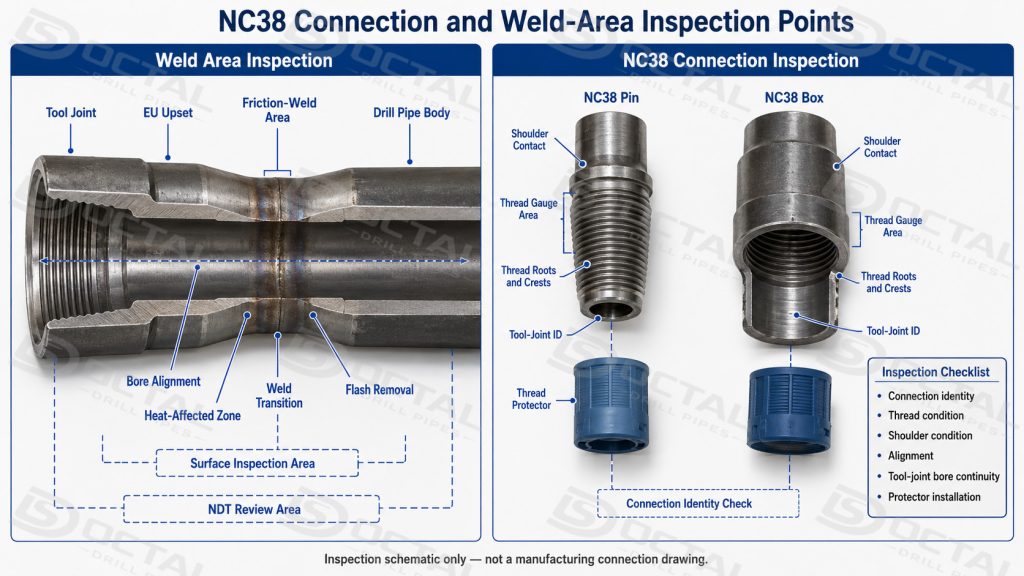
The separate tool joints are welded to the upset pipe body, creating one weld area at each end. Release inspection should review:
- external and internal flash removal;
- weld and heat-affected-zone condition;
- bore alignment through the transition;
- visible cracks, undercut or abnormal grinding;
- required NDT records;
- traceability to the finished joint or production lot.
A higher steel grade does not compensate for poor weld alignment, local wall loss or damaged connections.
NC38 Connection Inspection
The ordered pin and box ends use the NC38 rotary-shouldered connection for 3-1/2 inch drill pipe. Connection acceptance should confirm:
| Inspection Point | Release Check |
|---|---|
| Connection identity | NC38 marking and records agree |
| Threads | Correct form and gauge acceptance |
| Shoulder | Clean, flat and free from impact damage |
| Thread roots and crests | No dents, tears or corrosion |
| Tool-joint OD and ID | Match the approved configuration |
| Alignment | Pin and box axes align with the pipe body |
| Protectors | Installed after inspection |
The connection name alone does not define the complete tool-joint geometry. Tool-joint OD, ID and shoulder condition should also be checked before the drill pipe is combined with an existing NC38 string.
Release and Traceability Checklist
Before packing, the following points should be closed:
- Size, grade, weight, upset type, connection and length match the order.
- Pipe marking links to the heat number and material certificate.
- OD, wall thickness, straightness and length meet the acceptance criteria.
- The specified drift passes through the complete finished joint.
- Both weld areas have the required inspection records.
- NC38 threads and shoulders have passed the required checks.
- Joint marking, bundle tags and packing list show the same configuration.
The traceability chain should remain clear:
Joint marking → heat and production lot → MTC and inspection records → bundle tag → packing list
Packing and Delivery Through Mombasa
The Port of Mombasa provides an established entry point for Kenyan and regional cargo. For this shipment, packing should protect the larger tool-joint ends and prevent movement within the bundles.
Typical packing controls include:
- pin and box protectors on every joint;
- supports distributed along the pipe length;
- separators at tool-joint contact points;
- secure straps that do not load the thread protectors;
- visible bundle tags showing size, grade and connection;
- packing references matching the export documents.
The release package should include the MTC, dimensional report, drift result, connection and NDT records where required, packing list and shipping documents.
FAQ
Q1:What is the OD of 3-1/2 inch drill pipe?
A1:The nominal pipe-body OD is 3.500 in. / 88.9 mm. The tool-joint OD is larger and must be confirmed from the approved design.
Q2:What is the nominal weight of this configuration?
A2:The ordered pipe-body weight is 13.30 lb/ft, approximately 19.8 kg/m. This is not the total shipping weight of the complete joint.
Q3:Is the calculated body ID the same as the drift diameter?
A3:No. The calculated body ID is approximately 2.764 in. / 70.2 mm, while the drift is a separate acceptance dimension for the complete internal passage.
Q4:What connection is used for this order?
A4:The ordered connection is NC38. Compatibility should be confirmed through connection identity, thread gauging, shoulder condition and tool-joint dimensions.