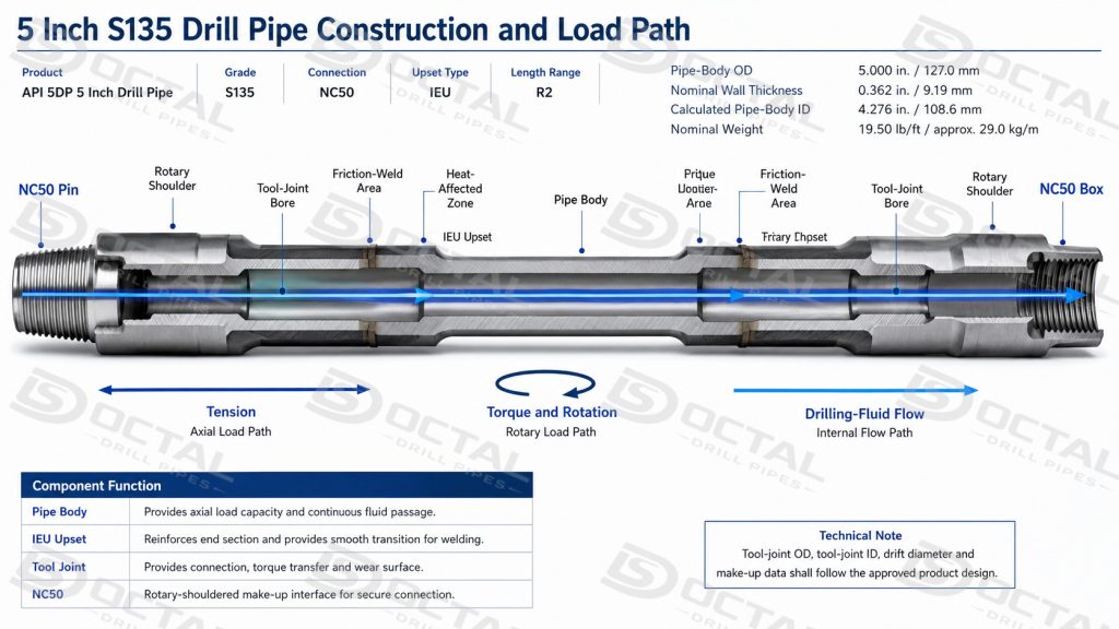
API 5DP 5 inch drill pipe is a finished drill-string assembly built from a heat-treated seamless alloy-steel pipe body, formed upset ends, and separate pin and box tool joints joined to the pipe ends by rotary friction welding. The 5.000 in. pipe body carries axial load and provides the drilling-fluid passage. The upset sections increase the available cross-section at the weld transition, while the heavier tool joints provide the rotary shoulders, connection geometry, external wear surface and repeated make-up and break-out interface.
During drilling, each joint transfers rotation and torque from the surface equipment to the bottomhole assembly, supports combined tensile, bending and pressure loads, and circulates drilling fluid toward the bit. Drill pipe is therefore selected as a complete assembly. Pipe-body grade, nominal weight, upset geometry, weld integrity, tool-joint OD and ID, connection condition and internal clearance must work together rather than being evaluated as separate specifications.
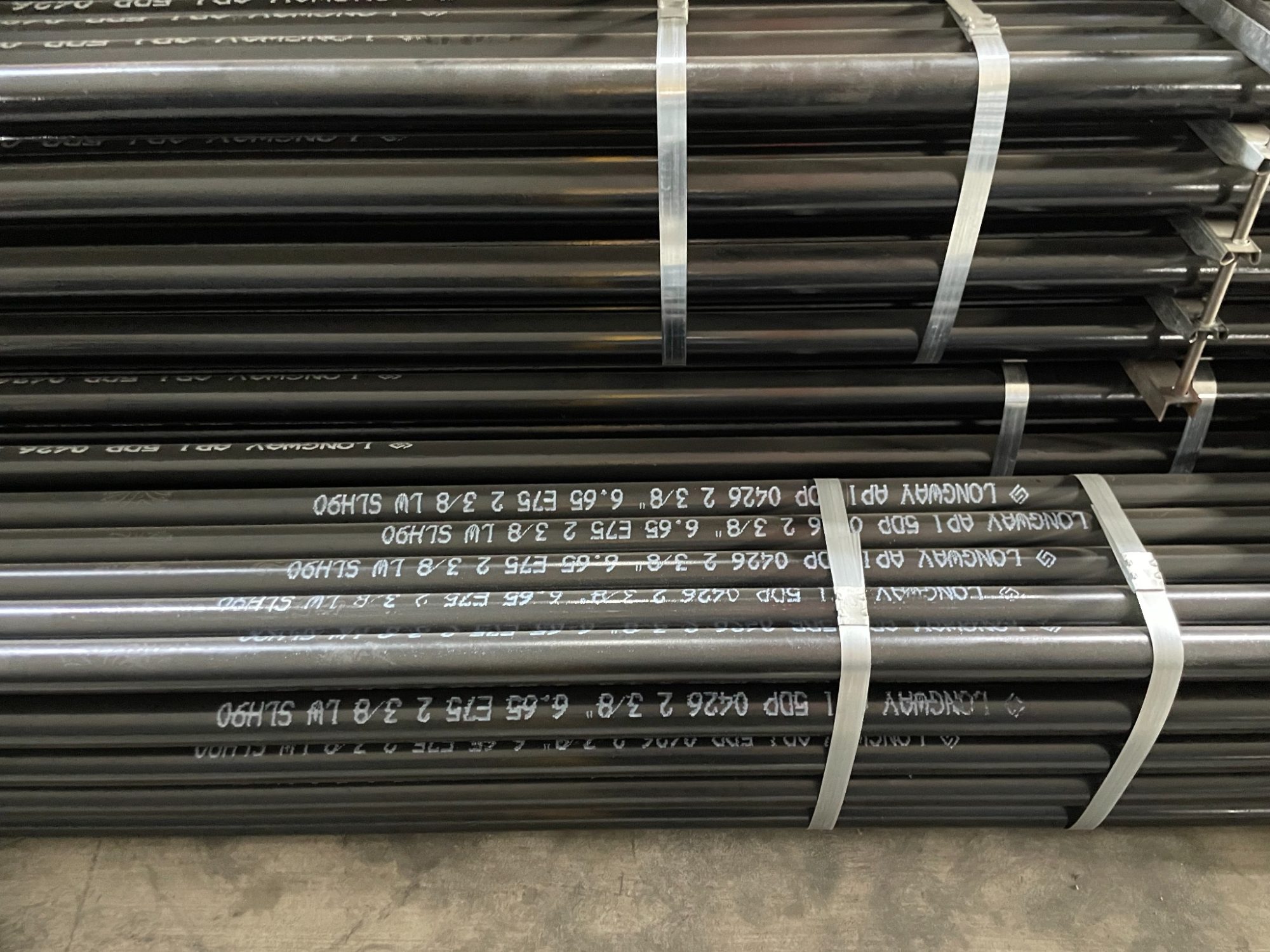
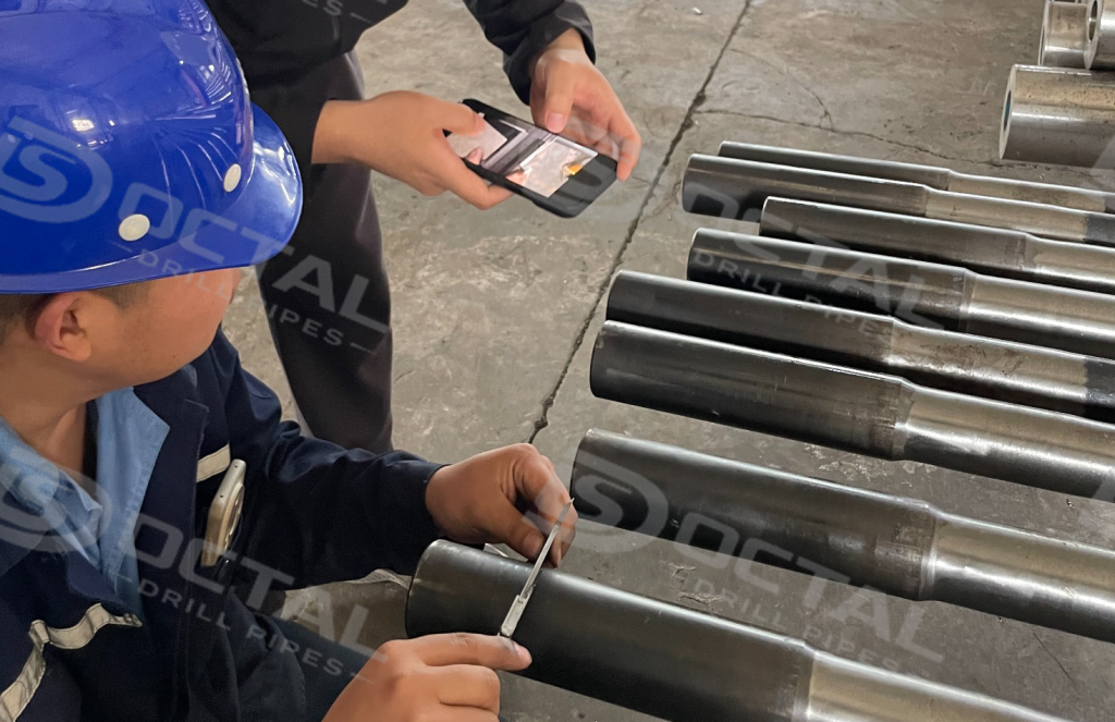
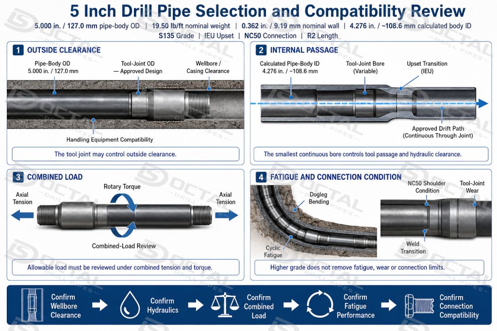
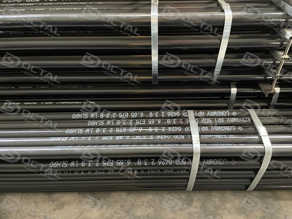
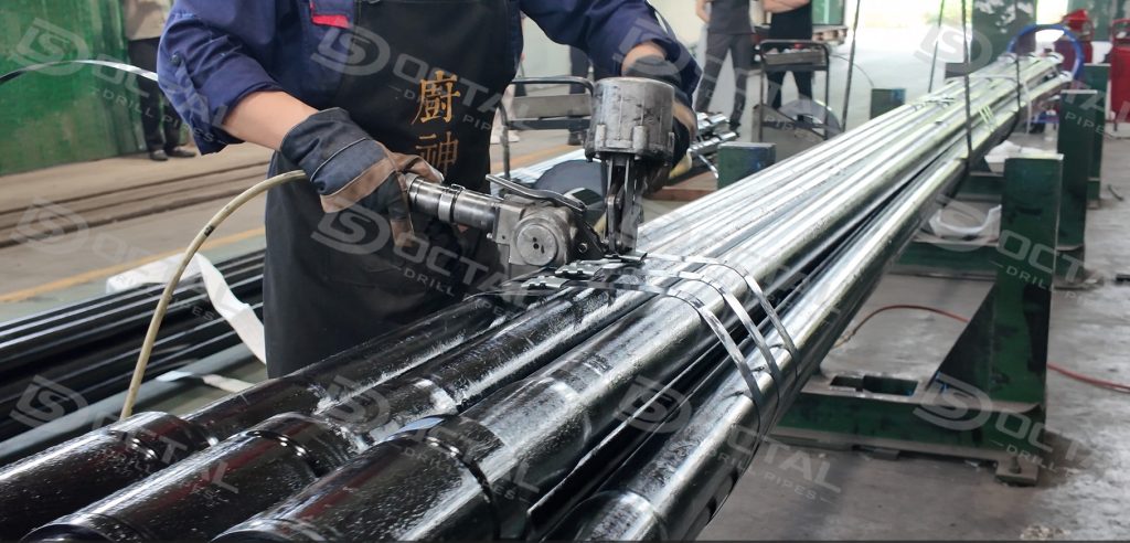
For delivery to the UAE, the approved configuration was API 5DP S135 drill pipe with a 5.000 in. pipe-body OD, 19.50 lb/ft nominal pipe-body weight, IEU upset ends, NC50 tool-joint connections and Range 2 length. The export lot completed final packing and document review for shipment to Khalifa Port in Abu Dhabi. Before release, the finished joints were checked against the approved order for body dimensions, upset and weld transitions, tool-joint geometry, NC50 compatibility, straightness and full-length internal clearance.
Order Overview
| Item | Order Details |
|---|---|
| Destination | Khalifa Port, Abu Dhabi, UAE |
| Product | API 5DP 5 Inch Drill Pipe |
| Pipe-Body OD | 5.000 in. / 127.0 mm |
| Nominal Weight | 19.50 lb/ft / approximately 29.0 kg/m |
| Nominal Wall Thickness | 0.362 in. / 9.19 mm |
| Nominal Pipe-Body ID | 4.276 in. / approximately 108.6 mm |
| Grade | S135 |
| Upset Type | IEU |
| Connection | NC50 |
| Length Range | R2 |
| Release Focus | Size, drift, NC50 identity, marking, packing and traceability |
The combination of 5 inch drill pipe, 19.50 lb/ft pipe body and NC50 connection is a widely recognized drilling configuration. Comparable standard connection tables also list 5.000 in. × 19.50 lb/ft drill pipe with NC50-family connections.
5 Inch Drill Pipe Construction and Specification Logic
The designation 5 inch drill pipe identifies the nominal outside diameter of the pipe body. It does not describe the complete outside envelope, internal passage or load capacity of the finished joint. Those characteristics depend on the full combination of body weight, wall thickness, grade, upset design, tool-joint geometry and connection.
The broader API 5DP 5 inch drill pipe dimensions, wall thickness and NC50 configuration provide the specification context for this 5.000 in. OD, 19.50 lb/ft S135 order. The final assembly still requires order-specific confirmation of upset geometry, tool-joint dimensions, internal clearance and inspection scope.
| Assembly Element | UAE Order Configuration | Engineering Function | Release Significance |
|---|---|---|---|
| Pipe body | 5.000 in. OD, 19.50 lb/ft | Carries axial load and forms the main drilling-fluid passage | Verify OD, wall thickness, straightness and body condition |
| S135 grade | High-strength API drill-pipe grade | Provides the specified pipe-body yield-strength level | Confirm heat, heat-treatment lot and mechanical-test traceability |
| IEU ends | Internal-external upset | Adds material at the pipe ends for load transfer and welding | Check upset geometry, minimum passage and transition alignment |
| Friction-welded tool joints | Separate pin and box components | Transfer torque and tension between the body and connection | Inspect weld area, heat-affected zone, flash removal and bore alignment |
| NC50 connection | Rotary-shouldered pin and box | Provides the make-up interface between adjoining joints | Confirm connection identity, gauge acceptance and shoulder condition |
| Range 2 length | Ordered length category | Defines the required finished-joint length range | Confirm measured finished length and bundle identification |
The 19.50 lb/ft value is a nominal pipe-body weight designation. It should not be used as the shipping weight of a complete joint because the finished assembly also includes two heavier tool joints and the upset sections.
The ordered IEU upset geometry for 5 inch drill pipe adds material on both the internal and external sides of the pipe end before the tool joint is welded. This provides additional section for the welded joint, but the internal portion of the upset can also reduce the passage below the calculated pipe-body ID. For this reason, the upset bore, weld transition and tool-joint bore must remain part of the drift review.
The 5.000 in. × 19.50 lb/ft configuration is commonly associated with NC50-family connections in industry reference configurations. However, the exact tool-joint OD, tool-joint ID, make-up data and remaining connection performance must follow the approved product design and inspection record for the actual order.
5 Inch Drill Pipe Size, Bore and Internal-Clearance Verification
For this order, 5 inch drill pipe refers to the nominal pipe-body outside diameter of 5.000 in. (127.0 mm). This dimension identifies the pipe body only. It does not represent the maximum outside diameter of the finished drill pipe, because the tool joints are larger than the pipe body and may become the controlling dimension for wellbore clearance, elevators, slips and other handling equipment.
The selected 19.50 lb/ft configuration has a nominal pipe-body wall thickness of 0.362 in. (9.19 mm). Based on these nominal dimensions, the calculated pipe-body inside diameter is approximately 4.276 in. (108.6 mm). These figures are used to identify the ordered configuration, but they are not sufficient on their own for final acceptance. Actual production release must be based on measured dimensions and the applicable purchase order, product specification and inspection plan.
Pipe-Body Dimensional Checks
Before packing, the pipe-body OD should be measured at several positions along the length and around the circumference using calibrated measuring equipment. This confirms that the body remains within the specified dimensional range and helps identify local out-of-roundness, handling deformation or abnormal sizing conditions.
Wall thickness should also be verified at the inspection points defined by the manufacturing procedure or project ITP. For finished drill pipe, the important question is not only whether the nominal wall is 0.362 in., but whether the measured minimum wall remains within the permitted requirement after rolling, upsetting and subsequent processing.
The dimensional record should therefore confirm:
- measured pipe-body OD at the required locations;
- minimum recorded wall thickness;
- ovality or local deformation where applicable;
- pipe-body straightness;
- finished length and range;
- absence of visible dents, sharp handling marks or surface damage.
Straightness is particularly important for a long drill-string member. Excessive bow can affect handling on the rig, rotation in the wellbore and alignment during connection make-up.
Internal Bore and Full-Length Drift
The nominal pipe-body ID of approximately 4.276 in. is a calculated value. It should not be treated as the guaranteed minimum passage through the complete drill pipe.
The smallest internal opening may occur at:
- the internal upset;
- the upset-to-body transition;
- the friction-weld area;
- the tool-joint bore;
- a local area affected by scale, machining or internal deformation.
For this reason, the finished pipe should be checked with the specified full-length drift mandrel. The drift must pass through the complete internal passage without forcing, machining contact or obstruction. A successful drift test confirms that the pipe can provide the minimum required clearance through the body, upset and tool joint.
This check is especially relevant when the drill string must pass downhole tools, wireline equipment or other assemblies with limited clearance. Using only the calculated pipe-body ID could overlook a restriction inside the upset or tool-joint bore.
5 Inch S135 Drill Pipe in Drill-String Design
5 inch S135 drill pipe may be selected as a main drill-string member where the well program requires the body size, hydraulic passage and load capacity associated with a 5.000 in. pipe body and an NC50 connection system. It is encountered in deep, directional and extended-reach drilling programs, but the size and grade alone do not confirm suitability for a particular well.
The S135 grade selection for 5 inch drill pipe in deep and directional wells should also account for suspended string weight, planned overpull, rotary torque, dogleg severity, fatigue exposure and connection capacity. The 135,000 psi minimum specified pipe-body yield strength does not by itself confirm the allowable performance of the complete joint.
The drilling program should review the following conditions together:
| Design Review | Practical Question | Why It Matters |
| Wellbore and casing clearance | Does the actual tool-joint OD clear the hole, casing and restrictions? | The tool joint, not the 5.000 in. pipe body, may control outside clearance |
| Internal hydraulics | What is the smallest continuous ID through the body, upset and tool joints? | The minimum passage affects pressure loss, flow area and downhole-tool clearance |
| Combined tension and torque | What hook load remains allowable at the expected drilling torque? | Tension and torque act together; separate maximum values cannot simply be combined |
| Bending and dogleg exposure | Where will the pipe rotate through high curvature? | Repeated bending raises fatigue demand at the upset, weld and connection |
| Tool-joint wear | What OD, shoulder and thread material remain after service or dressing? | Wear changes connection performance, clearance and classification |
| Handling compatibility | Do elevators, slips, tongs and protectors match the finished joint? | Body OD alone does not confirm rig-floor compatibility |
| Service environment | Is the material qualified for the actual corrosion or H₂S condition? | The S135 strength designation alone does not establish sour-service suitability |
Where the main string transitions toward the bottomhole assembly, 5 inch heavy weight drill pipe with an NC50 connection may be reviewed as the intermediate stiffness and weight section above the drill collars. Connection identity alone is not sufficient; tool-joint geometry, continuous bore, shoulder condition and approved make-up data must remain compatible with the adjacent 5 inch drill pipe.
A higher pipe-body grade increases the specified strength level, but it does not remove fatigue, connection, wear or corrosion limits. The final string design should therefore use the measured or approved body and tool-joint properties rather than relying only on the nominal description 5 inch S135 NC50 drill pipe.
NC50 Connection Inspection Before Shipment
An NC50 connection is released as a complete functional interface, not merely by confirming the stamped thread name. Inspection therefore follows three linked stages: identity confirmation, surface and geometry verification, and traceable release.
Connection Identity and Document Match
The inspector first confirms that both ends of the finished joint match the ordered NC50 configuration. The connection designation must agree across the following records:
- individual pipe marking;
- production traveler;
- machining or gauging report;
- inspection status;
- bundle tag;
- packing list.
This comparison is important when several 5 inch drill-pipe lots are handled in the same production or packing area. Pipes may share the same body OD while using different tool-joint connections, bores or customer-specific configurations.
Any mismatch between the physical connection and the documentation should be treated as a release hold point. The pipe should remain segregated until its identity has been verified and the records corrected.
Cleaning and Surface Examination
Before gauging, the thread, shoulder and accessible bore area are cleaned sufficiently to remove chips, dirt, heavy preservative and excess compound. Gauge contact surfaces must be visible and free from material that could produce a false reading.
The inspection then concentrates on the areas most likely to affect make-up or receiving acceptance:
| Inspection Area | Condition to Check | Practical Risk Controlled |
|---|---|---|
| Thread crests and roots | Burrs, dents, rolled edges, tearing or incomplete machining | Difficult engagement, galling or gauge rejection |
| Thread flanks | Local damage, abnormal tool marks or corrosion | Uneven load transfer after make-up |
| Rotary shoulder | Raised metal, impact dents, pitting or embedded particles | Incomplete or uneven shoulder contact |
| Pin nose and box entry | Handling damage, deformation or sharp edges | Cross-threading during initial engagement |
| Counterbore and bore transition | Steps, chips, eccentric machining or obstruction | Reduced drift clearance or disturbed internal flow |
| Connection surfaces | Rust, moisture, dirt or residual metal particles | Contamination and storage deterioration |
Light preservative or removable dirt may be cleaned before reinspection. A defect that affects thread engagement, shoulder contact, bore clearance or gauge acceptance must not be hidden by additional compound. It should be evaluated under the approved disposition or repair procedure and reinspected before release.
Gauging and Dimensional Verification
After the visual examination is accepted, the NC50 connection is checked with the applicable calibrated working gauges. The pin is inspected with the corresponding ring gauge, and the box with the matching plug gauge.
Before use, the inspector verifies:
- the gauge is correct for NC50;
- its identification number is legible;
- its calibration status is valid;
- the gauge surfaces are clean and undamaged;
- the connection and gauge are used under the required inspection conditions.
The measured gauge stand-off or gauge position is then compared with the acceptance criteria specified by the approved drawing, manufacturing procedure or applicable API 7-2 requirement.
A satisfactory visual appearance alone does not confirm connection geometry. Incorrect taper, lead, pitch diameter or thread form may still cause poor make-up, insufficient shoulder contact or incompatibility with the mating connection.
Connection Verification Matrix
Where required by the manufacturing plan or project ITP, the following characteristics are checked and recorded:
| Verification Item | Inspection Purpose | Typical Record |
|---|---|---|
| Pin and box gauge stand-off | Confirms working-gauge acceptance | Thread gauging report |
| Thread taper | Checks radial geometry along the thread length | Dimensional inspection sheet |
| Lead or pitch | Confirms axial thread progression | Thread measurement record |
| Thread height and profile | Detects incomplete or incorrect machining | Profile inspection result |
| Tool-joint OD and ID | Confirms external clearance and internal passage | Dimensional report |
| Counterbore or bore dimension | Confirms transition and drift compatibility | Bore inspection record |
| Connection concentricity | Checks alignment between thread and bore | Machining or final inspection report |
| Shoulder relationship | Confirms correct shoulder location and contact geometry | Connection inspection sheet |
The exact scope depends on the approved inspection procedure. The article should not imply that every optional measurement is mandatory for every shipment; however, all checks required by the purchase order and ITP must be completed before the connection is marked as accepted.
Individual Traceability and Reinspection Control
The inspection result should be linked to the individual pipe number, serial number or another traceable production identifier. A bundle-level note stating only “threads passed” is not sufficient when a single joint later requires investigation.
The record should identify, as applicable:
- pipe or serial number;
- NC50 pin and box designation;
- working-gauge identification;
- gauge calibration status;
- measured result or acceptance status;
- inspection date;
- inspector identification;
- repair or rework reference;
- final reinspection result.
Where a connection is repaired, its original rejection status should remain traceable. Release is permitted only after the repaired area has passed the required visual, dimensional and gauging checks.
Final Release Point
The NC50 connection is accepted for protection and packing only when:
- the physical connection matches the order and pipe marking;
- thread and shoulder surfaces are clean and free from rejectable damage;
- the required working-gauge result is acceptable;
- tool-joint bore and transition remain compatible with the specified drift;
- inspection records are complete and traceable;
- any repaired connection has passed documented reinspection.
Once accepted, the thread and shoulder are protected with the specified preservative or compound, and correctly fitting NC50 pin and box protectors are installed. The final packing check confirms that the protectors are secure and that the connection identification remains visible on the pipe and bundle records.Writing only “thread passed” on a bundle-level checklist provides weak evidence if one joint is later rejected during receiving inspection.
FAQ
Q1:What does 5 inch mean in 5 inch drill pipe?
A1:It refers to the nominal pipe-body OD of 5.000 in. / 127.0 mm. The finished tool-joint OD is larger and must be confirmed from the approved design.
Q2:What is the outside diameter of 5 inch drill pipe?
A2:The nominal pipe-body outside diameter is 5.000 in., equal to 127.0 mm. The tool-joint OD is larger and must be confirmed separately.
Q3:Is every 5 inch drill pipe supplied with NC50?
A3:No. NC50 is a common configuration, but the final connection must match the rig inventory, approved data sheet and drilling program.
Q4:What should be confirmed before shipping 5 inch drill pipe?
A4:Confirm nominal weight, grade, upset type, connection, tool-joint OD and ID, drift, length range, marking, inspection scope and document package.
Q5:Does S135 automatically make the drill pipe suitable for every deep or sour well?
A5:No. S135 defines the pipe-body strength grade. Well suitability also depends on combined load, fatigue, tool-joint condition, hydraulics, corrosion environment and any required sour-service qualification.