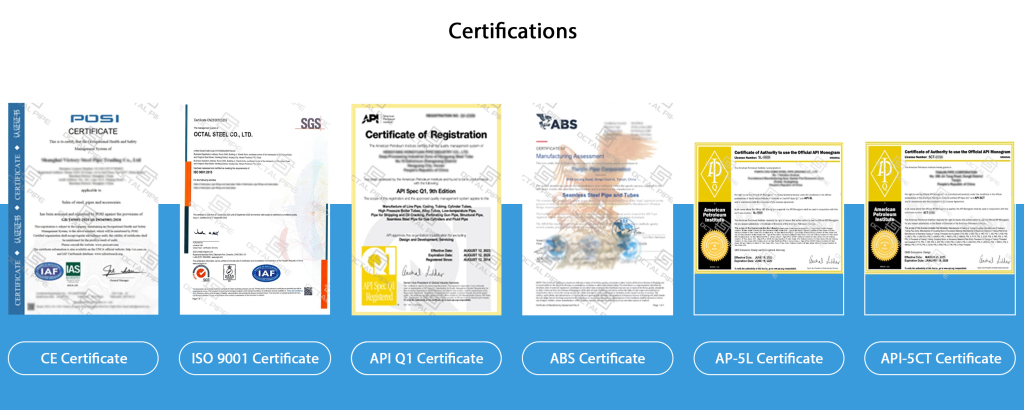
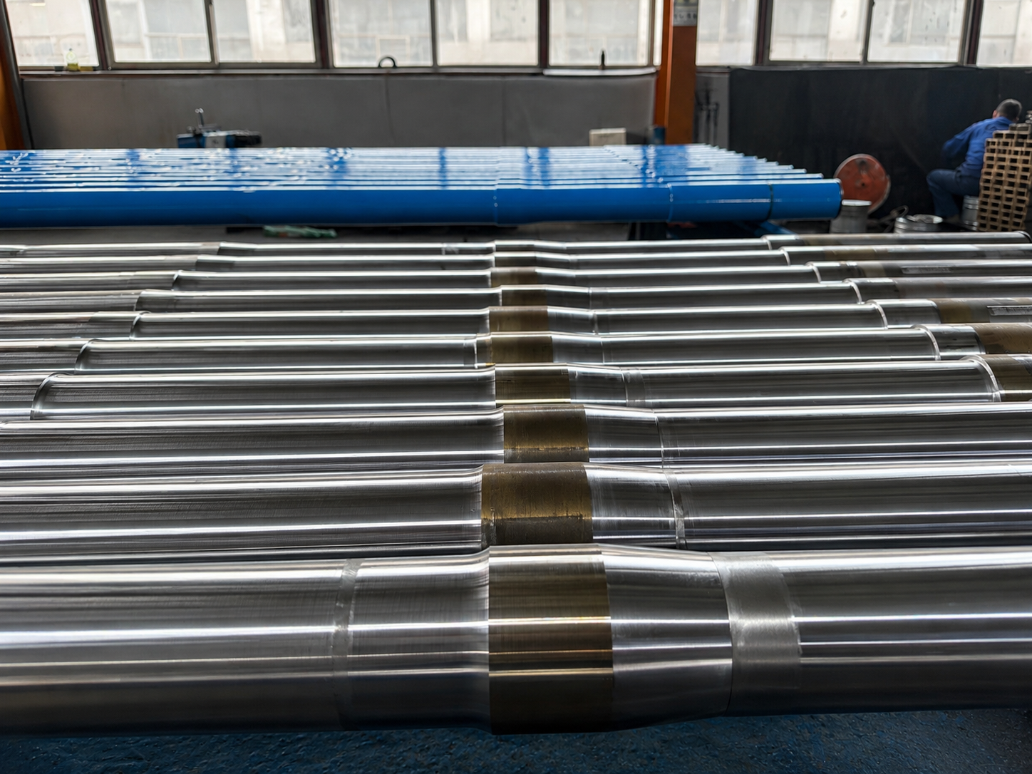
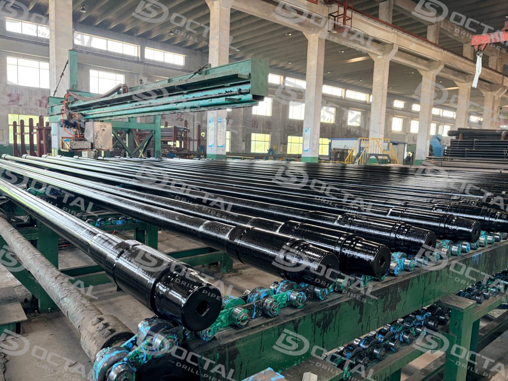
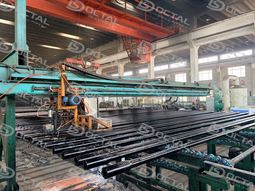
API 5DP drill pipe is a high-strength seamless alloy steel drilling tubular manufactured to API 5DP / ISO 11961. It consists of a heat-treated pipe body and weld-on tool joints, and is used in the drill string to transmit rotary torque, carry tensile load, circulate drilling fluid, and connect the rig equipment with the bottom-hole assembly. In medium-depth, deep, directional, horizontal and high-load oil and gas drilling programs, API 5DP drill pipe is selected by grade, size, upset type, tool joint connection, inspection level and traceability documents.
API 5DP Drill Pipe Grades and Specifications
Grade and Mechanical Properties
| Grade | Group | Min. Yield (MPa / ksi) | Max. Yield (MPa / ksi) | Min. Tensile (MPa / ksi) | Min. Elongation | Heat Treatment |
|---|---|---|---|---|---|---|
| E75 | 1 | 517 / 75 | 724 / 105 | 689 / 100 | 19.5% | Normalize, or N+T, or Q+T |
| X95 | 3 | 655 / 95 | 862 / 125 | 724 / 105 | 19.5% | Full-length Q+T after upset |
| G105 | 3 | 724 / 105 | 931 / 135 | 793 / 115 | 19.5% | Full-length Q+T after upset |
| S135 | 3 | 931 / 135 | 1138 / 165 | 1000 / 145 | 19.5% | Full-length Q+T after upset |
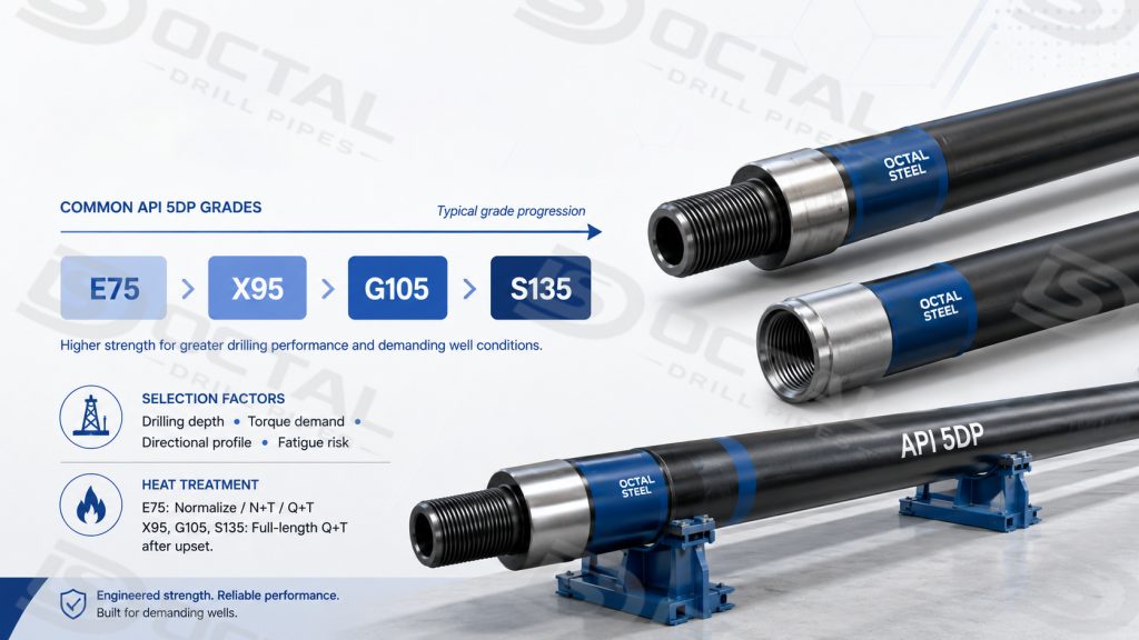
The standard market range of API 5DP drill pipe grades is centered on E75, X95, G105 and S135. These grades are not interchangeable labels. They represent different strength windows and are selected according to drilling depth, torque demand, buckling exposure, directional profile, and fatigue risk in the program.
For practical project use, E75 is more common where lower strength and easier handling are acceptable. X95 is often used for general directional and mid-depth work. G105 is a common transition grade when higher tensile capacity is needed without immediately moving into the highest API standard grade. S135 is the standard high-strength choice for deeper, extended-reach, or higher-stress drilling programs where tensile load, torque, and fatigue margin become more critical.
Size, Wall Thickness, and Standard Connections
| OD (in) | OD (mm) | Wall Thickness Range (mm) | Standard Connections | Length Ranges |
|---|---|---|---|---|
| 2 3/8 | 60.3 | 6.45 – 9.19 | NC26, IF | R1, R2 |
| 2 7/8 | 73.0 | 7.82 – 9.19 | NC31, IF | R1, R2 |
| 3 1/2 | 88.9 | 9.35 – 11.40 | NC38, IF | R1, R2, R3 |
| 4 | 101.6 | 9.35 – 11.40 | NC40 | R2, R3 |
| 4 1/2 | 114.3 | 9.35 – 12.70 | NC46 | R2, R3 |
| 5 | 127.0 | 9.19 – 12.70 | NC50 | R2, R3 |
| 5 1/2 | 139.7 | 9.17 – 12.70 | 5½ FH | R2, R3 |
| 6 5/8 | 168.3 | 10.59 – 12.70 | 6⅝ FH | R2, R3 |
Length ranges: R1 = 18–22 ft · R2 = 27–30 ft (most common) · R3 = 38–45 ft
Upset Types
The choice between IU, EU and IEU upset types changes the pipe-end bore, external envelope and tool-joint transition.
| Code | Configuration | Typical Application |
|---|---|---|
| EU | External upset — pipe end OD enlarged | E75, lighter-grade strings |
| IU | Internal upset — ID reduced at ends | Where consistent OD bore matters |
| IEU | Internal + external upset, both directions | Standard for X95/G105/S135; maximizes upset cross-section and connection fatigue resistance |
Product Specification Levels (PSL)
| PSL | What It Covers | When to Specify |
|---|---|---|
| PSL-1 | Dimensions, yield/tensile, basic impact per grade | Onshore standard wells |
| PSL-2 | PSL-1 + mandatory Charpy V-notch; tighter OD/wall tolerances; additional NDE | Directional, ERD, offshore baseline |
| PSL-3 | PSL-2 + full-length UT; enhanced chemistry; third-party witness available | HPHT, deepwater, sour-service |
Drill Pipe Manufacturing and Quality Control
Pipe Body and Heat Treatment
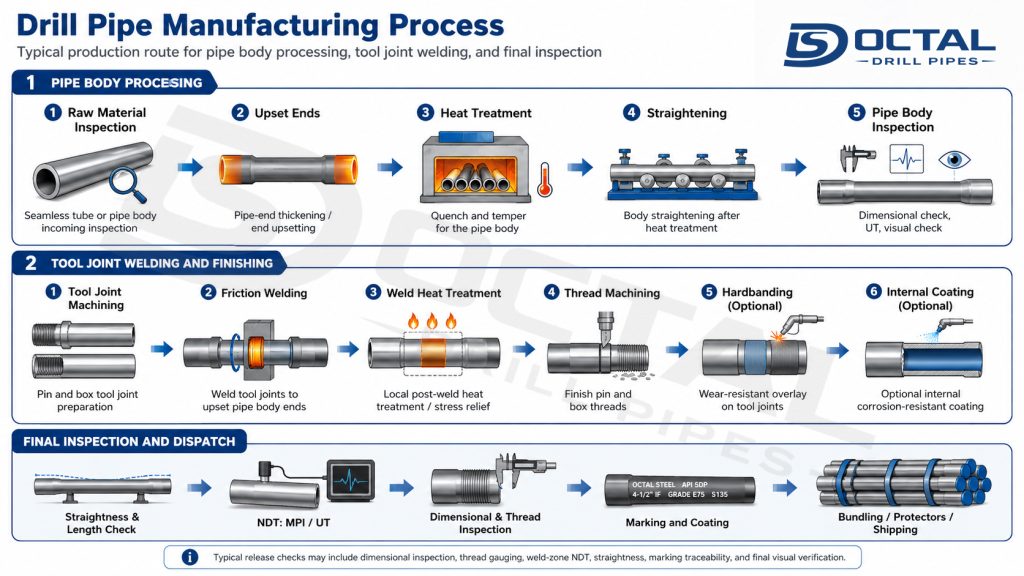
Pipe body is produced from seamless alloy steel tube. Fine-grain steel is mandatory under API 5DP: at least one grain-refining element — aluminium, niobium, vanadium, or titanium — must be present in quantities sufficient to produce a fine austenitic grain structure confirmed by post-heat-treatment metallographic check.
For Group 3 grades (X95, G105, S135), full-length quench-and-temper must be performed after upsetting, not on the green tube. This sequence matters because upsetting re-introduces heat-affected zone risk at the transition; Q+T performed before upsetting does not satisfy the specification. The furnace batch record — traceable to each pipe’s heat and lot marking — is the document that procurement uses to verify this at receipt inspection.
Tool Joint Weld-On and Dimensional Control
Tool joints are friction-welded onto the upset pipe ends. After welding, each pipe undergoes:
- Full-length UT of pipe body: 100% coverage per PSL-3 baseline and common project ITP requirement; spot coverage (10–25%) by agreement at PSL-1
- MPI on tool joints: 100% of tool joint OD and thread root surfaces; acceptance per API RP 7G-2 criteria
- Dimensional inspection: OD tolerance per API 5DP Table 7/8; wall thickness measured at minimum 12 locations per pipe; ovality ≤ 1.0% OD (standard project ITP threshold; PSL-3 and sour-service SRs apply tighter limits)
- Drift diameter verification: mandrel OD per size/weight table applied to 100% of pipe, confirming bore clearance for BHA pass-through
- Hydrostatic test: when specified in PO, at 1.5× design pressure with hold time defined in project ITP
Traceability Chain
Every pipe carries a continuous marking sequence — OD × wall × grade × upset type × connection × range × heat number × lot number × API monogram — that runs from pipe body through the MTC, NDT release record, and packing list heat/lot map. Procurement teams with ITP hold-and-witness points should specify MTC format at PO stage: EN 10204 3.1 is the baseline; 3.2 with nominated TPI co-signature is available for offshore and projects requiring third-party witnessed inspection.Final API 5DP drill pipe inspection before shipment reconciles NDT, dimensional results, drift verification, thread condition and traceability records with the marked joints.
Compliance and Standards
| Standard | Scope |
|---|---|
| API Spec 5DP, 2nd Ed. (2020) | Primary specification: grades, PSL requirements, dimensions, heat treatment, NDE |
| ISO 11961 | Identical international adoption of API 5DP |
| API Spec 7-1 | Rotary drill stem elements; tool joint dimensional requirements |
| API Spec 7-2 | Threading and gauging of rotary shouldered connections (NC, IF, FH, REG) |
| API RP 7G-2 | Inspection and classification of used drill stem elements |
| NACE MR0175 / ISO 15156 | Sour-service material requirements (applies when SR1/SR2 is invoked) |
| EN 10204 3.1 / 3.2 | MTC format; 3.2 requires TPI co-signature at mill inspection |
API 5DP Drill Pipe vs HWDP vs Drill Collar
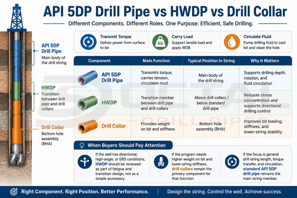
API 5DP drill pipe, heavy weight drill pipe and drill collars do not serve the same position in the drill string.Standard drill pipe is the main tubular used to transmit torque, carry tensile load, and circulate drilling fluid. HWDP is normally used as the transition member between standard drill pipe and drill collars, helping reduce stress concentration and improve string behavior in directional drilling. Drill collars provide concentrated weight on bit and stiffness in the lower string, so their role is closer to load application and BHA support than to general string transmission.
In practical string design, the selection is not drill pipe or HWDP or drill collar as interchangeable options. The real task is to place each component where it best supports torque transfer, tensile load, bending response, and fatigue control. HWDP is especially relevant in directional or high-angle wells because it provides a more gradual transition between the flexibility of drill pipe and the stiffness of drill collars.
| Component | Main Function | Typical Position in String | Why It Matters |
|---|---|---|---|
| API 5DP Drill Pipe | Transmits torque, carries tension, circulates mud | Main body of the drill string | Supports drilling depth, rotation, and fluid circulation |
| HWDP | Transition member between drill pipe and drill collars | Above drill collars / below standard drill pipe | Reduces stress concentration and supports directional drilling control |
| Drill Collar | Provides weight on bit and stiffness | Bottom hole assembly (BHA) | Improves bit loading, stiffness, and lower-string stability |
When Buyers Should Pay Attention
- If the well has directional, high-angle, or ERD conditions, HWDP should be reviewed as part of fatigue and transition design, not as a simple accessory.
- If the program needs higher weight on bit and lower-string stiffness, drill collars remain the primary component for that function.
- If the focus is general drill string length, torque transfer, and circulation, standard API 5DP drill pipe remains the main string member.
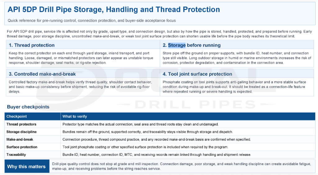
How to Store and Handle API 5DP Drill Pipe Before Running?
Applications
Directional and extended-reach drilling (ERD) — when the string is running through a wellbore with 30°–90° inclination, the pipe body cycles through bending every rotation. The primary failure mode is fatigue cracking initiating at the upset transition or the tool joint weld zone, not at mid-body. The procurement control that closes this risk: G105 or S135 IEU with PSL-2 Charpy verification at the specified test temperature, and 100% MPI on tool joints confirmed as a hold point in the project ITP before shipment release.
HPHT wells (>10,000 psi / >150°C reservoir conditions) — the string is carrying maximum tensile load while the tool joints are running at temperatures that reduce yield margin. S135 IEU at PSL-3 is the baseline specification. The risk that procurement must verify — and that Enpro’s page does not address — is whether full-length Q+T was performed after upsetting. A mill that heat-treats the green tube, then upsets, then ships without re-heat-treatment is technically non-compliant with API 5DP Group 3 requirements. The furnace batch record traceable to each pipe’s heat/lot number is the only document that closes this.
Sour-service drilling (H₂S-present formations) — where sulfide stress cracking (SSC) governs material selection. API 5DP Supplementary Requirement SR1 imposes a pipe body hardness cap of HRC ≤ 26; NACE MR0175 applies to the full drill stem assembly. E75 or controlled-chemistry X95 with SR1 is the typical specification. The most common procurement error is ordering S135 without explicit sour-service SRs — the string passes mechanical inspection at the mill, then fails hardness acceptance at rig site incoming inspection and is quarantined.
Offshore deepwater programs (>3,000 m water depth) — total drill string weight in a 6,000 m+ water column requires maximum tensile capacity at minimum OD. 5″ S135 IEU in R3 lengths is a standard specification for deep Gulf of Mexico and West Africa programs. Project documentation typically requires EN 10204 3.2 MTC with Lloyd’s or Bureau Veritas co-signature; this must be confirmed at PO stage since it cannot be retrofitted after mill production.
FAQ
Q: Does API 5DP compliance guarantee drill pipe connection interchangeability?
A: No. API 5DP specifies the finished drill pipe, while standardized rotary shouldered connection threading and gauging are controlled by API 7-2. The exact connection designation, tool joint dimensions and mating component must still be confirmed.
Q: Can S135 directly replace G105 or X95 drill pipe?
A: Not automatically. A higher API grade provides a higher specified strength level, but substitution must also consider pipe size and wall, upset configuration, tool joint connection, drill-string load, fatigue exposure and the project specification.
Q: Is standard API 5DP drill pipe automatically suitable for H₂S service?
A: No. Grade designation alone does not establish sour-service suitability. Current API 5DP requirements include specific controls for SS grades, including hardness, microstructure and H₂S-resistance testing, so sour service must be specified and qualified separately.
Q: Is API 5DP used to classify drill pipe after it has been in service?
A: API 5DP primarily defines the technical delivery requirements for manufactured drill pipe. Inspection and classification of used drill stem elements are addressed by API RP 7G-2, so in-service pipe should not be accepted solely against new-product API 5DP requirements.