X95 and G105 are API 5DP drill pipe body grades with minimum yield strengths of 95,000 psi and 105,000 psi respectively. X95 and G105 are API 5DP drill pipe grades defined by minimum yield strength: 95,000 psi (655 MPa) for X95 and 105,000 psi (724 MPa) for G105. With the same outside diameter and wall thickness, G105 provides approximately 10.5% more minimum pipe-body yield capacity, giving additional margin where X95 is insufficient under combined tension, torque and overpull.
Grade selection must be based on the complete drill pipe assembly, not pipe-body strength alone. Tool-joint capacity, connection torque, remaining wall thickness, fatigue exposure, well trajectory, H₂S conditions and inspection history can become the governing limits. X95 remains suitable when the calculated load margin is adequate; G105 is justified only when additional body strength is required and the connection and inspected condition can support it. Well depth or directional drilling alone is not a sufficient reason to upgrade the grade.
API 5DP X95 vs G105 Mechanical Properties
The grade number represents the specified minimum yield strength in thousands of psi.
X95 starts at 95 ksi and G105 at 105 ksi. Both belong to the higher-strength group of steel drill pipe grades, but G105 has a higher controlled yield and tensile-strength window.
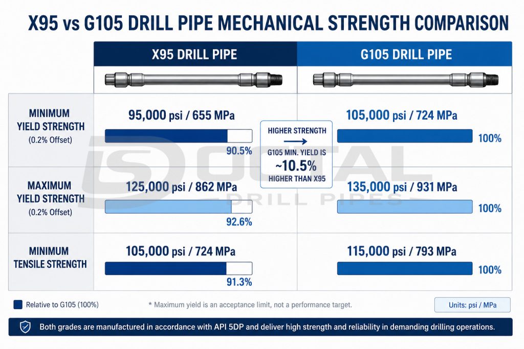
| Mechanical Property | X95 Drill Pipe | G105 Drill Pipe | Difference |
| Minimum yield strength | 95,000 psi / 655 MPa | 105,000 psi / 724 MPa | +10,000 psi / +69 MPa |
| Maximum yield strength | 125,000 psi / 862 MPa | 135,000 psi / 931 MPa | +10,000 psi / +69 MPa |
| Minimum tensile strength | 105,000 psi / 724 MPa | 115,000 psi / 793 MPa | +10,000 psi / +69 MPa |
| Relative minimum yield level | 1.00 | 1.105 | Approximately +10.5% |
| Typical grade position | Moderate-to-higher load | Higher-load drilling | G105 provides additional static margin |
The maximum yield value is an acceptance upper limit, not a performance target. Excessively high actual yield strength can affect the balance between strength, toughness and hardness, so the MTC should confirm that the material remains within the specified grade window.
What the 10 ksi Strength Difference Means
X95 drill pipe has a minimum yield strength of 95 ksi, while G105 is 105 ksi.
For the same OD, wall thickness and pipe-body geometry:
105 ÷ 95 = 1.105
This means the G105 pipe body has about 10.5% more minimum yield-based capacity than the equivalent X95 pipe body. The increase applies to calculated pipe-body tensile and torsional yield values when the dimensions are unchanged.
It does not mean the allowable field load can automatically be increased by 10.5%. The final limit may still be controlled by the connection, tool-joint dimensions, wall loss, fatigue condition, combined loading and the project design factor.
Same-Size X95 and G105 Performance Example
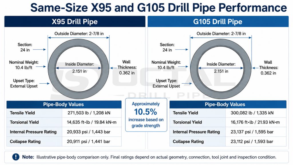
The following example uses a 2-7/8 in, 10.4 lb/ft, 0.362 in wall, 2.151 in ID, external-upset pipe body. It shows how the grade change affects calculated body performance while all dimensions remain unchanged.
| Pipe-Body Property | X95 | G105 | Increase |
| Tensile yield | 271,503 lb / 1,208 kN | 300,082 lb / 1,335 kN | 10.5% |
| Torsional yield | 14,635 ft-lb / 19.84 kN·m | 16,176 ft-lb / 21.93 kN·m | 10.5% |
| Internal pressure rating, published basis | 20,933 psi / 1,443 bar | 23,137 psi / 1,595 bar | 10.5% |
| Collapse rating, published basis | 20,911 psi / 1,441 bar | 23,112 psi / 1,593 bar | 10.5% |
These values demonstrate the grade effect, not a universal field operating limit. Final ratings must come from the approved product data sheet for the actual OD, wall thickness, upset, connection, tool joint and inspection condition. Published drill pipe data also separates pipe-body performance from tool-joint performance, which is why grade and connection cannot be reviewed as one number.
X95 vs G105 Under Actual Drill String Loads
A drill pipe does not operate under pure axial tension. During drilling, it can experience tension, torsion, internal pressure, bending, vibration, contact wear and intermittent compression at the same time.
| Load Condition | Effect of Changing X95 to G105 | Additional Review Required |
| Axial tension | Increases pipe-body yield capacity | Buoyed string weight, overpull and design factor |
| Rotary torque | Increases pipe-body torsional yield | Tool joint and connection torque limit |
| Internal pressure | Increases yield-based body margin | Actual wall thickness, washout and erosion |
| Collapse exposure | Can increase body resistance | External pressure, ovality and wall loss |
| Cyclic bending | Does not guarantee longer fatigue life | Dogleg severity, rotation cycles and surface condition |
| Combined tension and torque | Expands the body yield envelope | Combined-load interaction calculation |
| Connection loading | No automatic increase | Pin, box, shoulder and make-up torque |
| Used-pipe service | Depends on remaining section | Measured wall, class and inspection history |
The important distinction is between static strength and service reliability. G105 increases the static pipe-body strength level. It does not remove the fatigue damage created by severe doglegs, poor shoulder contact, corrosion pits, upset-transition defects or an under-designed connection.
X95 and G105 Drill Pipe Selection by Load Margin
The choice between X95 and G105 drill pipe should be based on calculated load margin, connection capacity and the actual condition of the drill string rather than grade name or well depth alone.
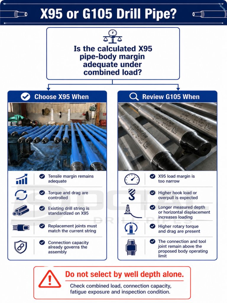
X95 remains the practical selection when:
- tensile load, torque and planned overpull remain within the allowable operating margin;
- the well is vertical or moderately directional with controlled torque and drag;
- dogleg severity is moderate and fatigue exposure is managed;
- replacement joints must match an existing X95 string;
- current tool-joint dimensions or connection capacity already govern the assembly;
- increasing the pipe-body grade would not raise the allowable system load.
G105 becomes justified when:
- buoyed drill string weight increases significantly;
- expected hook load or overpull approaches the X95 design margin;
- longer measured depth or horizontal displacement increases drag;
- heavier mud systems add axial loading;
- rotary torque, reaming or repeated high-load tripping becomes more demanding;
- additional pipe-body strength is required without moving directly to S135;
- the selected connection still has sufficient capacity for the higher-grade body.
A deep vertical well may remain within X95 limits, while a shorter extended-reach well can impose greater torque, drag and cyclic bending. Final selection should therefore follow the load model and also account for connection capacity, remaining wall thickness, fatigue history and inspection condition. A higher-grade pipe body does not automatically increase the allowable operating load when another component controls the drill string.
Connection Limits in X95 and G105 Drill Pipe
The drill pipe body, friction weld, tool joint and rotary shouldered connection form one assembly. Increasing the pipe-body grade does not automatically change the connection geometry or make-up torque.
For example, a G105 pipe body can have more torsional capacity than X95, but the complete joint remains limited by the weaker of:
- pipe-body torsional yield;
- pin torsional capacity;
- box torsional capacity;
- shoulder contact area;
- thread-root stress;
- allowable make-up torque;
- remaining tool joint OD after wear;
- friction weld and upset-transition condition.
This is particularly important when X95 and G105 joints use the same nominal NC or FH connection. The connection name alone does not confirm equal tool-joint OD, ID, torsional ratio or make-up torque.
A grade comparison should therefore confirm:
| Connection Item | Required Check |
| Connection designation | NC, FH, IF or project-specific thread |
| Tool joint OD and ID | Match the approved dimensional data |
| Pin and box geometry | Confirm interchangeability and remaining section |
| Shoulder condition | Check contact, damage and refacing history |
| Make-up torque | Use the approved value for the actual connection |
| Torsional ratio | Compare connection and pipe-body capacity |
| Thread gauge record | Confirm threading and gauging acceptance |
| Drift diameter | Confirm internal tool and circulation clearance |
| Hardbanding | Check type, location, cracking and wear condition |
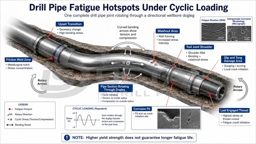
Fatigue Risks in X95 and G105 Drill Pipe
G105 provides a higher yield-strength margin before static yielding begins. Fatigue life, however, is controlled by repeated stress range and the number of cycles rather than yield strength alone.
Common fatigue locations include:
- the upset transition;
- the friction weld zone;
- the tool joint shoulder;
- the last engaged thread;
- areas with slip or tong damage;
- corrosion pits and washout;
- sections rotating through a dogleg.
A higher-grade pipe can still fail from fatigue while operating below its static yield limit. Severe dogleg rotation, vibration, lateral contact and surface damage can accumulate fatigue damage over many cycles.
What a Grade Upgrade Cannot Replace
Changing from X95 to G105 may increase pipe-body strength, but it does not replace:
- dogleg and rotary-speed control;
- connection and shoulder inspection;
- wall-thickness monitoring;
- weld-zone NDT;
- fatigue-history tracking;
- removal of damaged joints;
- corrosion and drilling-fluid control.
Grade selection should therefore be combined with inspection condition, connection capacity, remaining wall thickness and expected cyclic loading. A higher-strength pipe body can still fail when fatigue damage, corrosion or connection defects govern the assembly.
X95 and G105 in H₂S-Containing Service
Standard X95 and G105 grade names confirm mechanical strength levels. They do not, by themselves, confirm suitability for H₂S or sour-service drilling.
API 5DP Addendum 1 specifically points users toward ISO 15156 / NACE MR0175 for drilling equipment exposed to H₂S-containing fluids. Sour-service review can require controlled hardness, qualified metallurgy, heat-treatment records, microstructure verification and dedicated SS-grade testing.
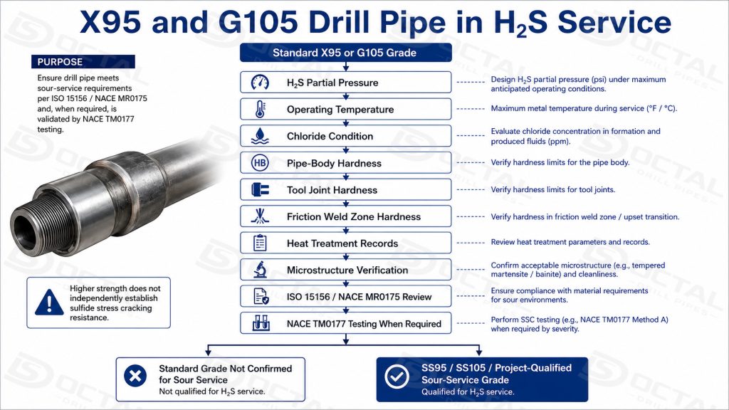
For H₂S exposure, the technical data sheet should distinguish between:
- standard X95 or G105;
- SS95, SS105 or another qualified sour-service grade;
- pipe-body requirements;
- tool-joint requirements;
- friction-weld-zone hardness;
- NACE TM0177 test requirements;
- operating temperature, H₂S partial pressure and chloride conditions.
Upgrading standard X95 to standard G105 does not solve a sour-service material problem. It raises strength; it does not independently establish sulfide stress cracking resistance.
Inspection Points for X95 and G105 Drill Pipe
X95 and G105 differ mainly in pipe-body strength. Final acceptance must also confirm the actual wall section, upset profile, friction-weld integrity, tool-joint dimensions, connection condition, internal clearance and traceability.
1. Pipe Body and Upset Transition
Factory verification
Measure OD, minimum wall thickness, straightness, ovality and upset dimensions. Wall thickness should be verified along the specified inspection path, with separate checks near upset transitions where automated coverage is limited.
The upset should also be examined for minimum section, concentricity, laps, folds and abrupt profile changes.
Buyer acceptance focus
The report should show actual measured values, minimum wall location and inspection coverage. These data confirm the real load-carrying section used for tensile, torsional, pressure and collapse review.
The upset transition deserves particular attention because the stiffness change makes it a fatigue-sensitive area.
2. Friction-Weld Zone
Factory verification
Inspect the complete weld circumference for alignment, weld-flash removal, surface defects and transverse cracking. Review wet fluorescent MPI, weld-zone hardness and any required additional NDT.
The record should link the pipe-body heat, tool-joint heat, weld lot and finished-joint identity.
Buyer acceptance focus
The buyer should verify the inspection method, coverage, procedure, result and disposition—not only a general “weld accepted” statement.
Cracking, excessive hardness or misalignment can become the controlling failure point, regardless of whether the pipe body is X95 or G105.
3. Tool Joint
Factory verification
Measure actual tool-joint OD, ID, bore, weld-neck section and remaining material after machining. Review hardness and internal and external surface NDT.
Dimensions should be compared with the approved tool-joint drawing.
Buyer acceptance focus
The actual OD and ID should provide the required torsional section, hydraulic clearance and compatibility with the existing drill string.
A higher-strength pipe body does not automatically increase tool-joint or connection capacity.
4. Pin, Box and Shoulder
Factory verification
Inspect thread roots, flanks, taper, lead, standoff and shoulder condition. Check for galling, corrosion, impact damage and previous refacing.
Calibrated gauges should be used for the applicable API 7-2 or project-specific connection.
Buyer acceptance focus
The gauge record should identify the connection, gauge number, calibration status and result.
Shoulder damage or repeated refacing may reduce torque transfer and sealing reliability even when the threads remain acceptable.
5. Drift Path and Internal Clearance
Factory verification
Pass the specified drift through the complete finished joint, including the pipe body, upset regions and tool-joint bores. Record the drift size, joint identity and result.
Buyer acceptance focus
The drift report should apply to the assembled drill pipe, not only the pipe body before welding.
This confirms tool passage and identifies restrictions caused by eccentric upset geometry, weld flash or an undersized bore.
6. Hardbanding
Factory verification
Check hardbanding type, position, width, height, continuity, cracking, spalling and wear.
Buyer acceptance focus
The hardbanding should provide wear protection without interfering with casing contact, handling or connection geometry.
7. Marking and Traceability
Factory verification
Maintain joint identification through grade, size, connection, pipe-body heat, tool-joint heat, weld lot and serial or joint number.
Buyer acceptance focus
The physical marking should match the MTC, mechanical tests, dimensional report, NDT, hardness, thread-gauge result, drift report and packing list.
This prevents X95 and G105 mix-up and allows individual nonconforming joints to be isolated.
Final Acceptance Principle
The acceptance package should clearly show:
what was inspected, where it was inspected, how it was inspected, which acceptance criterion was used and which joint the result represents.
A grade stencil supports identification, but it does not replace dimensional checks, weld inspection, connection gauging, drift testing or traceability.
X95 and G105 Drill Pipe Inspection-to-Shipment Release
X95 or G105 marking identifies the intended pipe-body grade, but shipment release depends on whether the pipe body, tool joint, friction weld, connection and inspection results remain linked to the same finished joint. This control begins before friction welding and continues until the joint number appears on the final packing list.
1. Material Identity Is Fixed Before Assembly
The pipe body and tool joint are normally received under separate heat numbers and test records. Before welding, the production traveler or joint record should capture:
- pipe-body heat number and test lot;
- tool-joint heat number;
- pipe size, nominal weight and upset type;
- required grade, X95 or G105;
- connection type and tool-joint dimensions;
- unique joint or production serial number.
This step prevents an approved X95 or G105 pipe body from being assembled with an unverified tool joint. Missing heat identification, mixed material or an MTC that cannot be linked to the physical component should place the material on hold before welding.
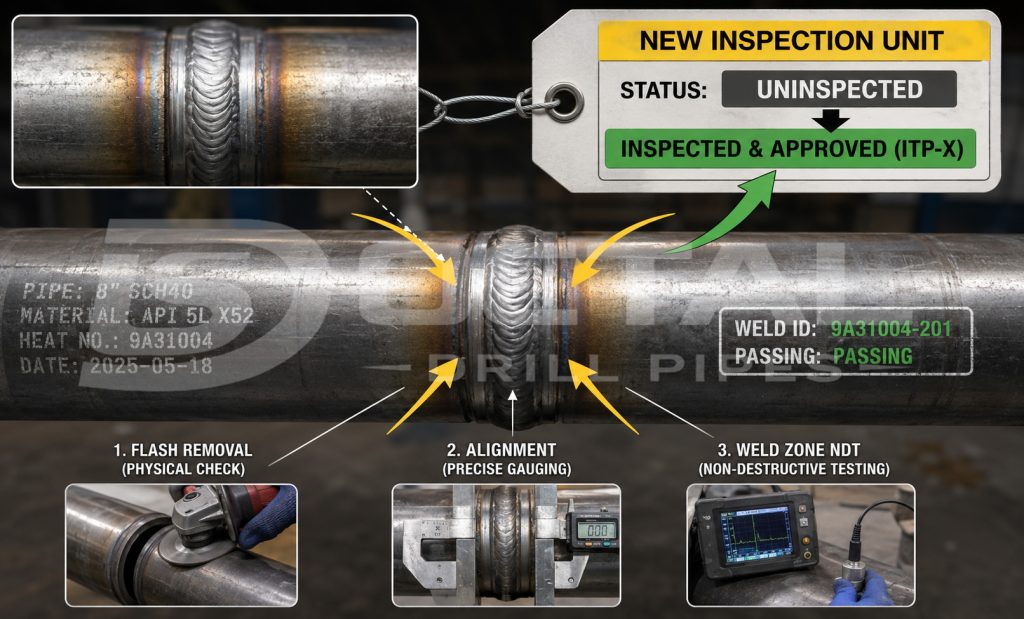
2. The Friction Weld Receives Its Own Inspection Status
After the tool joint is friction-welded to the upset pipe body, the assembly should be treated as a new inspection unit. The weld flash is removed, the joint is checked for alignment, and the weld zone is examined according to the project ITP.
| Weld-Zone Control | Actual Shop-Floor Check | Release Evidence |
|---|---|---|
| Alignment | Measure pipe-body and tool-joint concentricity after welding | Alignment or dimensional record |
| Weld profile | Check flash removal, transition profile and visible surface condition | Visual inspection result |
| Hardness | Take readings across the pipe body, weld zone and tool-joint side when specified | Hardness traverse or recorded values |
| NDT | Inspect the friction weld and adjacent transition area by the specified method | NDT report with joint or lot reference |
| Rework | Identify grinding, refacing or repair and repeat the affected inspection | Rework record and new acceptance result |
A repaired joint should not retain its original release status automatically. The affected dimension, weld area or connection feature must be reinspected, and the new result should be traceable to the same joint number.
3. Connection Acceptance Is Checked Separately from Grade Strength
The pipe body may meet X95 or G105 mechanical properties while the complete joint remains limited by the connection. Final connection inspection should therefore use the approved connection drawing and gauge requirements rather than the grade marking alone.
The practical checks normally include:
- actual tool-joint OD and ID;
- pin and box thread gauge results;
- shoulder face condition and contact surface;
- thread damage, galling, corrosion or refacing history;
- approved make-up torque reference;
- drift mandrel passage through the complete internal bore;
- hardbanding position, cracking and remaining condition.
Gauge identification and calibration status should be recorded where required by the inspection procedure. A thread marked NC50, for example, should not be accepted only because the connection name is correct; the tool-joint dimensions, shoulder condition and gauge results must also match the approved configuration.
4. Final Release Reconciles the Physical Joint with the Shipment File
Before packing, the final inspector should compare the actual joint marking with the released production and inspection records. The check is performed on the finished product, not only on office documents.
| Final Release Point | What Is Matched |
| Joint marking | Grade, size, nominal weight, range, connection and joint number |
| Pipe-body record | Heat number, chemical analysis and mechanical test results |
| Assembly record | Tool-joint heat, friction-weld lot and weld-zone inspection |
| Connection record | Tool-joint dimensions, thread gauges, shoulder and drift result |
| Surface condition | Hardbanding, coating, protectors and visible handling damage |
| Shipment record | Joint number, bundle number, quantity and packing-list entry |
The bundle tag should repeat the essential product identity and remain consistent with the packing list. When joint-level traceability is required, the packing list or attached joint list should identify which finished joints are contained in each bundle.
FAQ
F1: What is the main difference between X95 and G105 drill pipe?
Q1:X95 has a minimum yield strength of 95 ksi (655 MPa), while G105 is 105 ksi (724 MPa). For the same pipe-body dimensions, G105 provides about 10.5% more minimum yield strength, but the tool joint and connection do not automatically gain the same margin.
F2: When should G105 be selected instead of X95?
Q2:G105 is justified when buoyed string weight, hook load, overpull, torque or drag leaves insufficient margin in X95. The decision should follow the load model, not well depth alone.
F3:Does G105 have better fatigue life than X95?
Q3:Not necessarily. Fatigue is mainly controlled by repeated stress range, load cycles and local defects at the upset transition, friction weld, shoulder, threads, corrosion pits or dogleg sections.
F4:Can X95 and G105 use the same connection?
Q4:Yes, when the pipe size, upset, tool-joint dimensions and approved connection design are compatible. The actual tool-joint OD, ID, thread gauge result, shoulder condition and torque capacity must still be verified.
F5:Are X95 and G105 suitable for H₂S service?
Q5:The grade name alone does not confirm sour-service suitability. Hardness, heat treatment, SSC testing and the applicable ISO 15156 / NACE MR0175 requirements must be reviewed separately.