API 5DP Drill Pipe Grade Selection for deep and directional wells requires two different review paths. Deep-well selection is governed mainly by buoyed drill string weight, maximum hook load, planned overpull and the tensile capacity of the upper string. Directional-well selection adds torque-drag, dogleg-related bending, rotation time and fatigue near the upset transition, tool joint and thread shoulder.
The key decision is where X95 Drill Pipe, G105 Drill Pipe and S135 Drill Pipe fit within these load conditions. X95 remains relevant where directional load and torque are controlled, G105 covers many deeper or higher-load sections, and S135 is reviewed when hook load, long lateral rotation or ERD loading exceeds the available G105 margin. Pipe size, wall thickness, upset type, connection capacity, service condition and inspection records must support the same grade decision.
Deep and Directional Wells Require Different Grade Logic
Deep wells and directional wells do not place the same demand on a drill string. In a predominantly vertical deep well, the upper joints carry the accumulated buoyed weight of the drill string together with planned overpull. The first grade-selection question is whether the selected pipe body, wall thickness and tool joint provide sufficient tensile margin.
Directional wells introduce a combined load path. A joint rotating through a build section or dogleg carries axial tension while also transmitting rotary torque and passing through repeated bending cycles. In a long horizontal interval, torque and drag accumulate over measured depth, while extended rotation increases fatigue exposure near the upset transition, friction weld, thread shoulder and tool joint.
| Review Item | Deep Well | Directional or Horizontal Well |
|---|---|---|
| Primary load | Axial tension and hook load | Combined tension, torque, drag and bending |
| Main design input | Buoyed string weight, overpull and tensile margin | Torque-drag, dogleg severity and rotation time |
| Main mechanical concern | Insufficient upper-string tensile capacity | Cyclic fatigue and connection-side stress |
| Common grade range | G105 / S135 | X95 / G105 / S135 |
| Additional review | Tool joint tensile capacity | Connection torque, upset transition and shoulder contact |
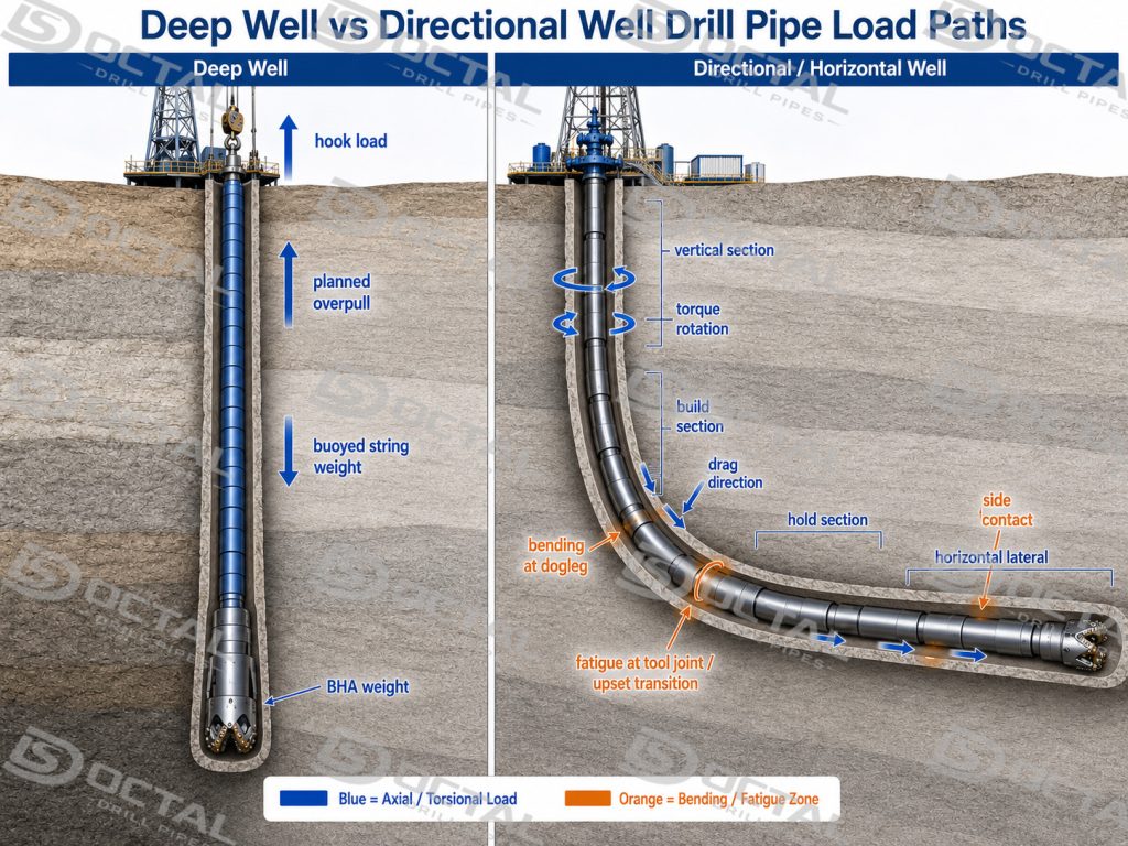
For deep wells, the grade boundary is set by buoyed string weight, maximum hook load, planned overpull and the remaining tensile capacity after wall-loss allowance. Directional wells require an additional review of torque-drag, dogleg severity, rotation time and fatigue concentration at the upset transition and tool joint. G105 remains suitable where the combined pipe-body and connection margins are adequate; S135 enters the review when higher hook load or long-lateral loading reduces those margins.
API 5DP Grade Strength Baseline
API 5DP grades are defined by specified yield and tensile limits for the drill pipe body. Minimum yield strength marks the start of permanent deformation, the maximum yield limit controls grade consistency, and minimum tensile strength verifies the required resistance before fracture. E75, X95, G105 and S135 should therefore be reviewed as separate acceptance windows and applied to the actual pipe size, remaining wall section and operating load.
| API 5DP Grade | Minimum Yield Strength | Maximum Yield Strength | Minimum Tensile Strength |
|---|---|---|---|
| E75 | 75 ksi / 517 MPa | 105 ksi / 724 MPa | 100 ksi / 689 MPa |
| X95 | 95 ksi / 655 MPa | 125 ksi / 862 MPa | 105 ksi / 724 MPa |
| G105 | 105 ksi / 724 MPa | 135 ksi / 931 MPa | 115 ksi / 793 MPa |
| S135 | 135 ksi / 931 MPa | 165 ksi / 1,138 MPa | 145 ksi / 1,000 MPa |
Pipe-body tensile capacity is governed by grade strength together with OD, wall thickness and wall loss, so a worn or lighter-wall S135 joint can retain less usable tensile margin than a thicker-wall G105 joint. Actual dimensions and wear allowance should be confirmed before the grade is matched to hook load and planned overpull.
How to Choose a Drill Pipe Grade for Deep Wells
Selection of API 5DP Drill Pipe Grades for Deep Wells begins with upper-string axial load. Total vertical depth alone does not determine the grade. Wells with similar depth can require different drill pipe specifications because of differences in pipe size, drill string configuration, drilling-fluid density, BHA weight and planned overpull.
Calculate the Upper-String Load
The deep-well load review should include:
- buoyed drill string weight
- maximum expected hook load
- planned overpull
- dynamic load allowance
- BHA weight
- remaining tensile design margin
- expected wall loss or wear allowance
Buoyancy reduces the effective drill string weight in fluid, but the upper joints still carry the accumulated load of the string below. Planned overpull also needs to be included because stuck-pipe recovery places additional tension on the same upper section.
Match the Load with Pipe-Body Capacity
Pipe-body tensile capacity is determined by grade strength, OD, wall thickness and remaining metal area. A heavier-wall G105 joint can provide greater tensile capacity than a lighter-wall S135 joint of another size.
The deep-well review should connect:
- pipe body OD
- actual wall thickness
- nominal weight
- minimum yield strength
- remaining wall after wear
- tool joint tensile capacity
- connection geometry
- current inspection condition
| Deep-Well Input | What It Controls | Effect on Grade Review |
|---|---|---|
| Buoyed string weight | Static axial load | Establishes the minimum tensile requirement |
| Maximum hook load | Upper-string loading | Helps separate G105 and S135 review |
| Planned overpull | Stuck-pipe recovery margin | Reduces the remaining tensile margin |
| OD and wall thickness | Pipe-body metal area | Changes capacity within the same grade |
| Tool joint strength | Assembly limit | Can control before pipe-body yield |
| Wear allowance | Remaining pipe-body capacity | Requires derating or closer inspection |
Deep-Well Grade Boundary
X95 Drill Pipe is suitable where the calculated upper-string tension, planned overpull and remaining wall section stay within the X95 design margin. It is mainly reviewed for medium-depth or lower-load deep wells using controlled string weight and standard connection demand.
G105 Drill Pipe is selected when X95 no longer provides enough tensile margin for the buoyed drill string weight and planned overpull. The review should include pipe-body cross-sectional area, remaining wall thickness, tool joint tensile capacity and the highest load carried by the upper string.
S135 Drill Pipe is reviewed when the combined hook load, overpull allowance and string weight approach the usable G105 capacity. Its higher pipe-body strength must be matched by the tool joint, shoulder contact, thread condition and upset-transition fatigue margin.
The G105–S135 boundary is therefore defined by calculated load and remaining section capacity, not by measured depth alone. Grade selection should be based on the actual string configuration, wall thickness, wear allowance and connection limit.
How to Choose a Drill Pipe Grade for Directional Wells
Selecting a drill pipe grade for directional drilling requires the load path to be reviewed by well section. Total measured depth alone does not represent drill pipe demand: the vertical section is dominated by axial tension, build and drop sections introduce repeated bending, and the hold or horizontal section combines torque, drag, wellbore contact and cumulative fatigue.
Load Path by Well Section
| Well Section | Dominant Load | Main Review |
|---|---|---|
| Vertical section | Axial tension and hook load | Buoyed string weight, overpull margin and pipe-body tensile capacity |
| Build / drop section | Tension plus repeated bending | Dogleg severity, build rate, rotation time and upset-transition fatigue |
| Hold section | Combined tension, torque and drag | Pick-up / slack-off load, rotary torque and connection capacity |
| Horizontal lateral | Sustained drag, contact and cumulative rotation | Torque accumulation, wear, fatigue exposure and tool joint condition |
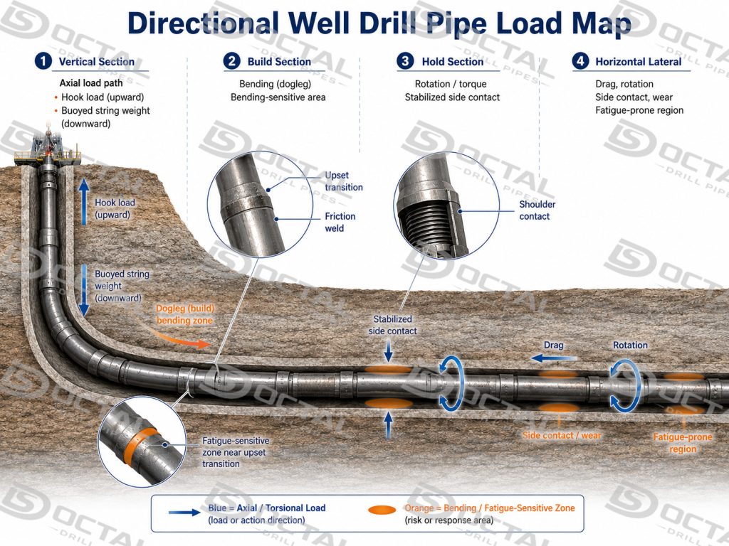
The grade review should follow the most severe section of the trajectory. A pipe that has enough tensile margin in the vertical section can still be limited by bending fatigue in the build section or by connection torque in the lateral interval.
Torque, Dogleg and Fatigue Review
Torque-drag analysis should compare pick-up load, slack-off load, rotating load, sliding load and maximum rotary torque with the pipe-body and connection limits. Tool joint geometry, shoulder contact, thread condition and make-up torque determine the connection-side capacity; increasing the pipe-body grade does not increase these limits automatically.
Dogleg severity and rotation time determine the number and intensity of bending cycles. Fatigue demand concentrates near:
- the pipe-body-to-upset transition
- the friction-weld area
- the tool joint transition
- the thread root
- the shoulder contact area
Long laterals add sustained wellbore contact, accumulated torque-drag, abrasive wear and repeated rotation. These conditions require fatigue and connection review even when the calculated axial stress remains below the pipe-body yield limit.
Directional-Well Grade Boundary
| Directional-Well Condition | Main Control Point | Common Grade Review |
|---|---|---|
| Short directional section with moderate dogleg | Tensile margin and standard connection condition | X95 / G105 |
| Higher torque with controlled bending exposure | Tool joint torque capacity and shoulder contact | G105 |
| Long horizontal section | Torque-drag, rotation time and cumulative fatigue | G105 / S135 |
| Severe dogleg or high build rate | Upset-transition and connection-side fatigue | Grade plus detailed fatigue review |
| ERD profile | Combined tension, torque, drag and connection loading | S135 or special material route |
| Restricted bore or tool passage | Tool joint ID, upset type and drift diameter | Grade plus dimensional review |
X95 Drill Pipe remains suitable for controlled directional sections where tensile load, rotary torque and dogleg exposure remain within its verified margin. G105 Drill Pipe for directional drilling is commonly reviewed when combined tension and torque increase but fatigue and connection demand remain controlled. S135 Drill Pipe enters the review when long lateral rotation, ERD torque-drag or severe bending reduces the remaining G105 margin.
The final selection should confirm that the pipe body, upset transition, tool joint and connection support the same load path. A higher grade does not correct insufficient connection torque, restricted internal clearance or fatigue-sensitive geometry.
G105 vs S135 for Deep and Directional Wells
The difference between G105 and S135 extends beyond the 30 ksi increase in minimum yield strength. The selection boundary depends on where the first mechanical limit occurs in the drill string.
| Selection Factor | G105 Review Basis | S135 Review Basis |
|---|---|---|
| Hook load | G105 retains adequate calculated tensile margin | Hook load approaches the reviewed G105 margin |
| Deep-well profile | Higher axial load with controlled connection demand | Higher string load or reduced G105 margin |
| Directional profile | Controlled dogleg, torque-drag and rotation exposure | Long lateral, ERD or stronger combined loading |
| Torque | Connection and shoulder remain within the reviewed range | Higher torque requires matched tool joint and shoulder capacity |
| Fatigue | Rotation and bending exposure remain controlled | Long rotation or severe bending requires closer fatigue review |
| Service condition | Standard environment without governing sour or low-temperature requirement | Strength review combined with hardness, toughness and service qualification |
| Documentation | Standard mechanical test and inspection package | Closer review of hardness, impact, tool joint and traceability records |
For G105 vs S135 for deep wells, the main dividing point is the available tensile margin after string weight, hook load and planned overpull are included.
For G105 vs S135 for directional wells, the dividing point also includes torque-drag, dogleg severity, lateral length, rotation exposure and connection capacity.
S135 Drill Pipe for ERD provides a higher pipe-body strength window, but ERD performance still depends on tool joint matching, connection torque, fatigue resistance and dimensional control. A stronger pipe body does not correct an undersized tool joint, damaged shoulder or fatigue-sensitive upset transition.
When X95 Drill Pipe Is Still Enough
X95 Drill Pipe remains suitable for medium-depth directional wells where build and hold sections are controlled, lateral length is limited, and calculated tensile, torque and overpull margins remain adequate. The review should also confirm that dogleg severity, cumulative rotation and connection demand remain within the standard operating range.
Moving to G105 or S135 does not correct restrictions caused by tool joint wear, poor shoulder contact, limited internal clearance or incomplete inspection records. X95 should remain in the grade review when pipe-body strength is not the controlling limit.
Grade Selection Must Match Pipe Design and Connection Capacity
An API 5DP drill pipe specification must match the pipe-body grade with OD, wall thickness, upset geometry, tool joint dimensions and connection capacity. OD and wall thickness determine the tensile area, while the upset, tool joint, thread and shoulder control internal clearance and torque transfer. A higher grade adds little value when one of these areas becomes the first mechanical limit.
| Review Area | Why It Matters |
|---|---|
| OD, wall thickness and nominal weight | Control tensile area, string weight, hook load and internal clearance |
| IU / EU / IEU upset | Change end geometry, local bore and fatigue-sensitive transition shape |
| Tool joint OD / ID | Control connection strength, external clearance, bore area and tool passage |
| Drift diameter | Confirms internal passage through the completed assembly |
| Connection type and make-up torque | Define thread engagement, torque transfer and operating limit |
| Shoulder contact | Transfers compressive and torsional load across the connection |
| Weld and transition areas | Require inspection because geometry changes concentrate cyclic stress |
| Thread and gauge condition | Confirm connection geometry and make-up compatibility |
For G105 and S135, the first mechanical limit can move from the pipe body to the upset transition, friction weld, tool joint or thread shoulder. A higher pipe-body grade adds little value when connection torque, internal clearance or fatigue-sensitive geometry does not support the same load case.
An S135 pipe body does not create an S135-level drill string when the connection or tool joint controls the operating limit. Pipe-body tensile capacity and connection torque capacity must be reviewed as separate but connected parts of the same load path.
Grade Selection Must Match Pipe Design and Connection Capacity
Pipe-body grade cannot be reviewed separately from OD, wall thickness, upset geometry, tool joint dimensions and connection capacity. These items determine the metal area carrying tensile load, the internal clearance through the upset and tool joint, and the way torque and bending load transfer through the complete assembly.
| Review Area | Why It Matters |
|---|---|
| OD, wall thickness and nominal weight | Control tensile area, string weight, hook load and internal clearance |
| IU / EU / IEU upset | Change end geometry, local bore and fatigue-sensitive transition shape |
| Tool joint OD / ID | Control connection strength, external clearance, bore area and tool passage |
| Drift diameter | Confirms internal passage through the completed assembly |
| Connection type and make-up torque | Define thread engagement, torque transfer and operating limit |
| Shoulder contact | Transfers compressive and torsional load across the connection |
| Weld and transition areas | Require inspection because geometry changes concentrate cyclic stress |
| Thread and gauge condition | Confirm connection geometry and make-up compatibility |
For G105 and S135, the first mechanical limit can move from the pipe body to the upset transition, friction weld, tool joint or thread shoulder. A higher pipe-body grade adds little value when connection torque, internal clearance or fatigue-sensitive geometry does not support the same load case.
An S135 pipe body does not create an S135-level drill string when the connection or tool joint controls the operating limit. Pipe-body tensile capacity and connection torque capacity must be reviewed as separate but connected parts of the same load path.
API 5DP Drill Pipe Grade Selection Summary
The selected API 5DP grade is acceptable only when the controlling load, remaining pipe-body margin, connection capacity and inspection records support the same drill string configuration. Deep-well selection focuses on hook load and overpull, while directional-well selection also requires torque-drag, dogleg fatigue and connection review.
| Well Condition | Initial Grade Range | Governing Review | Final Confirmation |
|---|---|---|---|
| Medium-depth directional well | X95 / G105 | Torque, dogleg bending and tensile margin | Connection capacity and tool joint condition |
| Deep well | G105 / S135 | Buoyed string weight, hook load and planned overpull | Remaining wall section and tool joint tensile capacity |
| Long horizontal well | G105 / S135 | Torque-drag, rotation time and cumulative fatigue | Upset transition, shoulder contact and thread condition |
| Severe dogleg section | Grade plus fatigue review | Build rate, curvature and repeated bending cycles | Transition-area NDT and connection inspection |
| ERD well | S135 or special material route | Combined tension, torque, drag and fatigue | Pipe body, tool joint and connection must support the same load path |
Deep-well selection is governed mainly by axial tensile margin, while directional and ERD selection requires additional control of torque-drag, dogleg fatigue and connection-side loading. The selected grade should be supported by actual dimensions, load calculations and traceable inspection records.
FAQ
F1:Which API 5DP drill pipe grade is normally selected for deep wells?
Q1:G105 Drill Pipe is commonly reviewed when the calculated upper-string tension and planned overpull exceed the practical range of X95. S135 Drill Pipe enters the review when buoyed string weight, hook load and overpull reduce the remaining G105 margin. OD, wall thickness, wear allowance and tool joint tensile capacity must be fixed before the two grades are compared.
F2:Is G105 or S135 better for directional and horizontal wells?
Q2:G105 is suitable where torque-drag, dogleg bending and cumulative rotation remain within the verified pipe-body and connection margins. S135 is reviewed for longer laterals, ERD profiles or higher combined loading that reduces the available G105 margin. The higher grade still requires matching tool joint, shoulder and thread capacity.
F3:Can S135 Drill Pipe solve high torque or severe dogleg conditions by itself?
Q3:No. S135 increases pipe-body tensile strength, but it does not automatically increase connection torque capacity or remove fatigue concentration at the upset transition, weld area and thread shoulder. High-torque or severe-dogleg service requires separate review of make-up torque, shoulder contact, tool joint dimensions, rotation time and transition-area fatigue.
F4:What records should support API 5DP drill pipe grade selection?
Q4:The grade should be supported by a traceable chain of pipe marking, heat number, MTC, tensile test, Charpy or hardness records where required, NDT, dimensional inspection, tool joint and thread inspection, and final release records. These documents confirm that the selected grade, remaining wall section and connection refer to the same delivered drill pipe.