
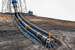
Drill string working principle converts surface rotation, axial movement, and hydraulic pump power into controlled cutting action at the drill bit. The process does more than turn a long column of pipe. It must deliver usable torque and weight to the bottom of the hole while circulating enough drilling fluid to cool the bit, power downhole tools, and carry newly cut rock back to the surface.
So, how does a drill string work under actual drilling conditions? The rig starts circulation, rotates the string or powers a downhole motor, lowers the bit onto the formation, and gradually transfers part of the suspended load to the cutting structure. The bit then removes rock while the returning fluid clears the bottom of the hole. These actions occur together. How effectively these inputs reach the bit depends on the complete drill string structure, including the drill pipe, transition section, and BHA. Increasing weight on bit usually raises torque demand and may increase vibration, while changing rotary speed or pump flow can affect bit speed, motor differential pressure, hydraulic power, cuttings transport, and equivalent circulating density. The complete drill string components and structure determine how effectively these mechanical and hydraulic inputs reach the bit.
How the Drilling Cycle Begins
The drilling cycle starts before the bit touches the bottom. Establishing stable circulation and confirming unrestricted returns allow the crew to identify abnormal pressure or flow behavior before applying rotary and axial load.
A normal drilling sequence includes:
- Establishing circulation: The mud pumps deliver fluid through the surface pressure system and down the drill string.
- Confirming pressure response: Standpipe pressure should stabilize at a level consistent with the planned flow rate, mud properties, drill string geometry, and installed downhole tools.
- Starting rotation: The top drive begins rotating the string, or circulating fluid starts the downhole motor.
- Approaching bottom: The driller lowers the string while monitoring hook load, torque, pressure, and block position.
- Applying bit load: After the bit contacts the formation, additional downward movement transfers part of the suspended string load to the bit.
- Establishing a drilling response: Rotary speed, weight on bit, flow rate, and tool differential pressure are adjusted until the bit drills steadily.
- Monitoring the system: Surface and downhole measurements are compared with the expected response throughout the run.
| Drilling stage | Main input | Expected response | Abnormal indication |
|---|---|---|---|
| Circulating off bottom | Pump flow | Stable pressure and full returns | Unexpected pressure rise, pressure loss, or reduced returns |
| Rotating off bottom | Surface rotary speed | Predictable no-load torque | High or cyclic torque |
| Tagging bottom | Controlled lowering | Hook-load reduction | Sudden impact or irregular load change |
| Applying bit load | Further slack-off | Increasing torque and penetration | No penetration response, vibration, or motor stall |
| Stable drilling | Balanced WOB, RPM, and flow | Consistent ROP and manageable dynamics | Rising torque, erratic pressure, or unstable ROP |
The readings should form a coherent pattern. A reduction in hook load without a corresponding drilling response may indicate poor load transfer. A pressure increase without additional WOB may point to a restricted nozzle, a loaded motor, or solids accumulating around the BHA.
How Surface Rotation Becomes Bit Rotation
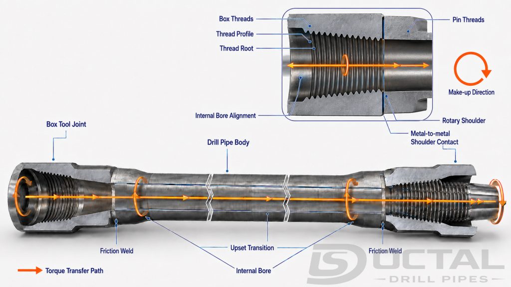
The top drive applies rotary speed and torque to the upper end of the drill string. Tool joints and each drill pipe body transfer that torque through the string until it reaches the BHA and drill bit.
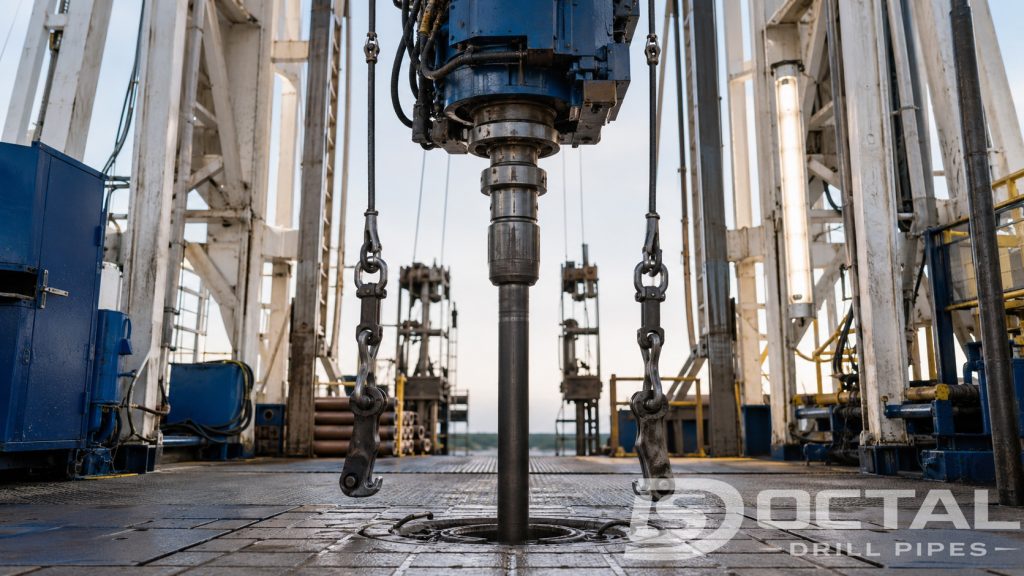
The drill string does not behave like a completely rigid shaft. Applied torque causes the long tubular string to twist elastically, while contact with the wellbore creates friction that can slow the lower string and bit. String length, pipe dimensions, connection geometry, well trajectory, and borehole contact all affect this response.
If friction temporarily holds the bit while the surface continues rotating, the drill string stores torsional energy. Once that energy overcomes the resisting force, the lower string accelerates and releases part of the stored energy. This stop-and-accelerate motion is called stick-slip. It explains why instantaneous bit speed can vary significantly even when the surface RPM display appears stable.
Mechanical Power Transmitted Through the String
Rotary power depends on torque and rotational speed. The following calculations illustrate how the same drill string can transmit very different power levels as operating parameters change.
| Calculated operating case | Torque | Rotary speed | Mechanical power | Metric equivalent |
|---|---|---|---|---|
| Lower-power case | 20,000 ft-lb | 80 rpm | 305 hp | 227 kW |
| Intermediate case | 30,000 ft-lb | 120 rpm | 685 hp | 511 kW |
| Higher-power case | 40,000 ft-lb | 150 rpm | 1,142 hp | 852 kW |
| Calculation item | Formula |
|---|---|
| Rotary power | Torque in ft-lb × RPM ÷ 5,252 |
| Metric conversion | Horsepower × 0.7457 |
These are calculated power values, not allowable drilling limits. The approved surface torque must remain below the lowest applicable operating limit among the pipe body, tool joints, connections, crossovers, jars, motors, measurement tools, and bit connection.
The same surface power can also produce different downhole results. Some energy reaches the bit and breaks rock. Some is lost through friction between the string and wellbore. Another part appears as vibration, elastic deformation, heat, and repeated contact with the borehole wall.
Why Bit Speed Can Differ from Surface Speed
The relationship between surface RPM and bit RPM changes with the drilling method.
| Drilling mode | Surface string condition | Source of bit rotation | Important operating behavior |
|---|---|---|---|
| Surface rotary drilling | String rotates continuously | Top drive or rotary table | Average bit speed may approach average surface speed, but torsional vibration can cause instantaneous differences |
| Motor drilling with rotation | String rotates while fluid powers the motor | Surface drive plus downhole motor | Bit speed includes both surface and motor rotation |
| Sliding mode | String remains substantially stationary | Downhole motor | Reactive torque changes toolface orientation |
| Rotary steerable drilling | String normally rotates continuously | Surface drive with downhole steering | Continuous rotation reduces prolonged stationary contact but does not eliminate vibration |
During motor drilling, bit RPM cannot be determined from surface RPM alone. Motor speed depends on flow rate, motor geometry, applied bit load, differential pressure, internal leakage, and power-section condition.
Under load, a positive-displacement motor normally rotates more slowly than its no-load theoretical speed. If the bit resistance exceeds the torque available from the motor, the motor may stall. Surface indications commonly include increasing standpipe pressure and a sudden loss of penetration.
How Surface Movement Creates Downhole Bit Load
Weight on bit develops when the driller lowers the suspended string after the bit contacts the formation. Part of the load that was previously carried by the hoisting system is transferred to the bit, so the measured hook load decreases.
In a near-vertical well with limited friction, the difference between off-bottom and on-bottom rotating hook load can provide a useful surface estimate of WOB. In directional and horizontal sections, that subtraction does not show exactly how much force reaches the bit.
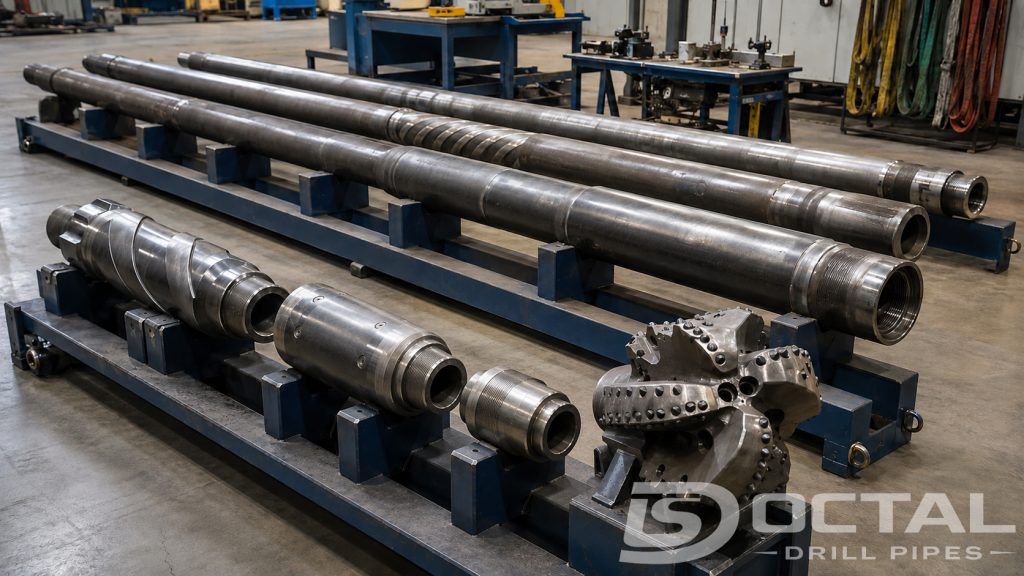
Contact between the string and the low side of the hole creates friction. Some surface slack-off force is therefore consumed in moving pipe along the wellbore. Ledges, keyseats, doglegs, cuttings beds, stabilizer contact, and pipe buckling can further reduce or destabilize load transfer.
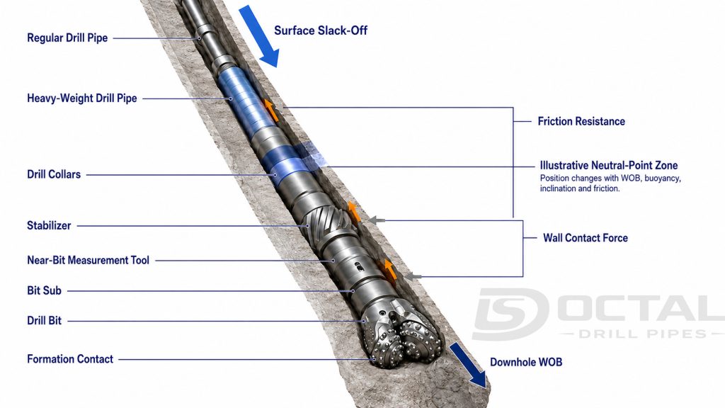
Simplified Load-Transfer Example
The following example shows why surface-indicated WOB may exceed the estimated load delivered to the bit in a deviated well.
| Load item | Calculated or assumed value |
|---|---|
| Rotating hook load off bottom | 300,000 lbf |
| Rotating hook load on bottom | 260,000 lbf |
| Surface-indicated WOB | 40,000 lbf |
| Modeled incremental slack-off friction | 8,000 lbf |
| Simplified estimated load reaching the bit | 32,000 lbf |
| Estimated transfer efficiency | 80% |
This is an illustrative calculation, not a universal friction allowance. Actual transfer efficiency can change as inclination, contact force, mud lubricity, pipe movement, hole condition, and cuttings accumulation change.
For critical operations, downhole WOB measurements provide a more direct indication of the force near the bit. Torque-and-drag modelling is still needed because one sensor describes a local condition rather than the complete axial load distribution along the string.
Unstable load transfer may appear as:
- WOB changes without a proportional ROP response
- Repeated hook-load fluctuations
- Bit bounce or axial shock
- Sudden motor differential-pressure changes
- Toolface instability while sliding
- Rising pickup or slack-off drag
- Alternating compression and tension near the lower string
Increasing surface WOB is not always the correct response. If cuttings beds or wellbore friction are preventing load transfer, additional slack-off may increase pipe compression without meaningfully increasing downhole WOB.
How Hydraulic Energy Reaches the Bit
Drilling fluid circulation supplies hydraulic energy and maintains the flow path required for drilling. Mud moves from the pumps through the standpipe, rotary hose, and top drive before entering the drill string bore. It then passes through the drill pipe, BHA tools, motor, measurement equipment, valves, and bit nozzles.
The fluid returns through the annulus between the string and the wellbore. On the way back to the surface, it transports cuttings and contributes to wellbore pressure control.
Pressure is consumed throughout this circuit. Internal pipe friction, tool-joint restrictions, motor power sections, telemetry devices, valves, bit nozzles, and annular flow all require part of the available standpipe pressure.
Illustrative Pressure Budget
The following pressure budget is a calculated example. It shows how the available surface pressure can be distributed across the complete circulation system.
| Pressure component | Example pressure loss |
|---|---|
| Surface equipment | 300 psi |
| Drill pipe and tool joints | 500 psi |
| Motor and downhole tools | 1,200 psi |
| Bit nozzles | 2,000 psi |
| Annular return path | 500 psi |
| Calculated standpipe pressure | 4,500 psi |
The example does not define a universal pressure allocation. Actual pressure loss changes with flow rate, fluid rheology, temperature, internal diameter, pipe roughness, tool configuration, nozzle area, hole geometry, and cuttings concentration.
Bit hydraulic horsepower can be estimated from the flow rate and pressure drop across the bit.
| Hydraulic calculation item | Example value |
|---|---|
| Flow rate | 500 gal/min |
| Bit pressure drop | 2,000 psi |
| Calculated bit hydraulic horsepower | 583 hp |
| Metric equivalent | 435 kW |
| Calculation | Formula |
|---|---|
| Bit hydraulic horsepower | Flow in gal/min × bit pressure drop in psi ÷ 1,714 |
| Metric conversion | Horsepower × 0.7457 |
The calculated hydraulic horsepower represents the rate of hydraulic energy delivered across the bit nozzles. It does not show how efficiently the jets clean the cutting structure or bottom of the hole. Nozzle orientation, total flow area, bit profile, formation response, and distance from the nozzle outlet to the bottom also matter.
Why Flow Rate Alone Does Not Confirm Hole Cleaning
A higher flow rate normally increases internal and annular velocity, but drilling fluid circulation must be evaluated as a complete transport system.
Effective cuttings removal depends on:
- Actual rather than nominal hole diameter
- Annular clearance around the drill pipe and BHA
- Hole inclination and pipe eccentricity
- Mud density and rheological properties
- Cuttings size, density, and shape
- Rate of penetration and solids-generation rate
- Drill string rotation and reciprocation
- Cuttings-bed thickness in high-angle sections
- Available pressure and equivalent circulating density
As ROP increases, the bit produces more cuttings per unit of time. A flow rate that cleaned the hole at a lower ROP may become inadequate after drilling performance improves. Rising torque and drag can therefore be a hole-cleaning warning rather than evidence that the formation has become harder.
How the Bit Combines Mechanical and Hydraulic Energy
The bit removes rock only when its mechanical and hydraulic inputs work together.
Weight on bit pushes the cutting structure into the formation. Rotation moves cutters or inserts across the bottom. Torque overcomes the rock’s resistance to cutting. Fluid jets clear broken material from the bit face, and annular flow transports the cuttings away from the bottom.
| Energy or load input | Action at the bit | Result when insufficient | Result when excessive |
|---|---|---|---|
| Weight on bit | Establishes cutter or insert engagement | Shallow cutting and low penetration | Cutter overload, bounce, buckling, or motor stall |
| Rotary speed | Produces repeated cutter movement | Low cutting frequency | Heat, vibration, accelerated wear, or stick-slip |
| Torque | Overcomes rotational cutting resistance | Bit slowdown or stall | Connection overload or torsional damage |
| Bit hydraulic power | Cleans and cools the cutting structure | Bit balling and recutting of solids | Excessive pressure demand or formation erosion |
| Annular flow | Transports cuttings toward the surface | Cuttings-bed formation and pack-off risk | High annular pressure loss and ECD |
The relative importance of each input changes with the bit type and formation.
Fixed-cutter bits remove rock mainly by shearing. Roller-cone bits use indentation, crushing, and chipping. Impregnated bits grind hard formation while exposing new abrasive material as the matrix wears. Each mechanism requires a different balance of load, speed, torque, and hydraulic cleaning.
How Drilling Parameters Interact
Changing one drilling parameter rarely affects only one part of the process.
Increasing WOB can deepen cutter engagement and improve ROP, but it also raises torque demand. Increasing RPM creates more cutter passes, but it can amplify torsional or lateral vibration. Increasing flow can improve cooling and cleaning while raising standpipe pressure and annular pressure loss.
| Parameter change | Intended effect | Related change | Possible adverse result |
|---|---|---|---|
| Increase WOB | Increase depth of cut | Higher torque demand | Stick-slip, bit damage, buckling, or motor stall |
| Increase surface RPM | Increase cutter passes | Higher mechanical power | Heat, whirl, and connection fatigue |
| Increase pump flow | Improve cooling and cuttings transport | Higher pressure loss and motor speed | Excessive standpipe pressure or ECD |
| Increase bit nozzle restriction | Increase pressure drop and jet velocity | Higher hydraulic energy at the bit | Reduced allowable flow or pump-pressure margin |
| Increase ROP | Drill more footage per unit time | Higher cuttings-generation rate | Poor hole cleaning if circulation is unchanged |
| Rotate the string while drilling | Reduce stationary wall contact | Higher dynamic contact and torque | Tool-joint wear and lateral vibration |
This interaction is why drilling parameters should be adjusted from trends rather than isolated readings. Raising WOB because ROP has fallen may make the problem worse if poor cleaning is already increasing bit resistance.
How Mechanical Specific Energy Describes Drilling Efficiency
Mechanical specific energy estimates the mechanical energy required to remove a unit volume of rock. It combines the contribution from axial bit load with the contribution from rotary torque.
A rising MSE trend can indicate that more energy is being consumed without a proportional increase in rock removal. Possible causes include dull cutters, bit balling, vibration, poor load transfer, inefficient parameters, or a formation change.
Calculated MSE Example
| Calculation input | Example value |
|---|---|
| Bit diameter | 8.500 in |
| Calculated bit area | 56.75 in² |
| Weight on bit | 30,000 lbf |
| Torque | 8,000 ft-lb |
| Rotary speed | 120 rpm |
| Rate of penetration | 120 ft/hr |
| Calculated axial contribution | 529 psi |
| Calculated rotary contribution | 53,149 psi |
| Calculated total MSE | 53,678 psi |
| MSE calculation | Formula |
|---|---|
| Bit area | π × bit diameter² ÷ 4 |
| Axial contribution | WOB ÷ bit area |
| Rotary contribution | 120π × torque × RPM ÷ bit area × ROP |
| Total MSE | Axial contribution + rotary contribution |
The calculated result is an operating comparison value, not a universal acceptance limit. Formation strength, bit design, well trajectory, measurement accuracy, and vibration all affect interpretation. MSE is most useful as a trend within the same hole section rather than as an isolated number compared across unrelated wells.
Why Surface Data Can Misrepresent Downhole Conditions
The rig measures the input side of a long, flexible system. The bit responds at the opposite end after torque, axial force, and hydraulic energy have passed through thousands of feet of pipe and multiple downhole tools.
Surface torque therefore does not equal bit torque. Surface WOB does not always equal downhole WOB. Surface RPM may hide rapid changes in instantaneous bit speed.
| Surface observation | Possible downhole condition | Information needed for confirmation |
|---|---|---|
| Stable surface RPM with irregular ROP | Stick-slip or uneven cutter engagement | Downhole RPM and torsional vibration |
| Cyclic surface torque | Torsional oscillation, formation change, or stabilizer contact | Torque frequency and downhole dynamics |
| Added surface WOB with little ROP response | Poor load transfer, bit balling, or dull cutters | Downhole WOB, bit differential pressure, and cuttings |
| Rising standpipe pressure | Motor loading, nozzle restriction, plugging, or changing rheology | Flow check and pressure-loss breakdown |
| Falling standpipe pressure | Washout, nozzle loss, pump issue, or reduced fluid viscosity | Flow balance and pressure integrity |
| Increasing pickup and slack-off drag | Cuttings bed, tight hole, ledge, or wellbore instability | Trip trends and hole-cleaning evaluation |
| Stable surface values with tool damage | High-frequency downhole vibration not visible at surface | Downhole shock and vibration record |
One abnormal signal can have several possible causes. The diagnosis becomes stronger when torque, pressure, WOB, ROP, return flow, cuttings condition, and downhole measurements point to the same event.
Common Dynamic Problems in a Working Drill String
Dynamic problems do not always begin with an obvious surface alarm. Some develop gradually as the formation, hole condition, or operating parameters change.
| Dynamic condition | What happens downhole | Typical surface evidence | Likely operational consequence |
|---|---|---|---|
| Stick-slip | The bit alternately stops and accelerates | Cyclic torque and unstable ROP | Cutter damage and torsional fatigue |
| Bit bounce | The bit repeatedly loses and regains contact | Hook-load or WOB fluctuation | Impact damage and inconsistent depth of cut |
| Whirl | The bit or BHA rotates around an eccentric path | Erratic torque and lateral vibration | Gauge wear and BHA damage |
| Motor stall | Bit resistance exceeds available motor torque | Pressure rise and sudden ROP loss | Motor overload and stopped bit rotation |
| Poor hole cleaning | Cuttings accumulate in the annulus | Increasing torque, drag, and ECD | Pack-off and stuck-pipe risk |
| Torsional resonance | The string responds near an unfavorable natural frequency | Repeating speed and torque oscillation | Connection and tool fatigue |
| Axial load-transfer loss | Surface slack-off does not reach the bit efficiently | WOB increase with limited ROP response | Compression and buckling above the BHA |
The correct response depends on the diagnosed mechanism. Reducing WOB may help a motor stall, but it will not correct inadequate annular transport. Increasing flow may improve cleaning, but only when the pressure and ECD margins allow it.
How Engineers Stabilize the Drilling Process
Stable drilling requires controlled adjustments supported by several measurements. The operating team should determine whether lost performance originates at the bit, within the BHA, along the drill string, or in the hydraulic return path.
Useful operating practices include:
- Compare actual torque, drag, pressure, and ROP with the pre-job model.
- Change one principal drilling parameter at a time when conditions permit.
- Allow the surface and downhole response to stabilize before judging the result.
- Check circulation and cuttings returns before assuming that higher torque comes from harder formation.
- Distinguish surface-indicated WOB from load measured near the bit.
- Review downhole vibration before increasing RPM or WOB.
- Treat sudden pressure loss as a possible washout or flow-path integrity problem.
- Reduce the drilling rate when cuttings generation exceeds the available transport capacity.
- Reassess operating parameters after major changes in inclination, hole size, BHA configuration, bit type, or mud properties.
The most efficient setting is not necessarily the highest available WOB, RPM, torque, or flow. It is the combination that converts the greatest useful share of mechanical and hydraulic energy into stable rock removal while keeping the string and downhole tools within their approved operating envelopes.
FAQ
Q: How does a drill string work during rotary drilling?
A: The surface drive rotates the string and transmits torque to the bit. Controlled slack-off supplies weight on bit, while drilling fluid flows through the string and returns through the annulus with the cuttings.
Q: Why can bit RPM differ from surface RPM?
A: Elastic twist, wellbore friction, stick-slip, and downhole motor rotation can separate instantaneous bit speed from the RPM measured at the surface.
Q: Why does surface WOB not always equal downhole WOB?
A: Friction, wellbore contact, doglegs, cuttings beds, and pipe buckling can absorb part of the applied surface load before it reaches the bit.
Q: How does drilling fluid help the drill string work?
A: Drilling fluid powers applicable downhole tools, cools and cleans the bit, transports cuttings, supports pressure control, and carries measurement signals in mud-pulse telemetry systems.