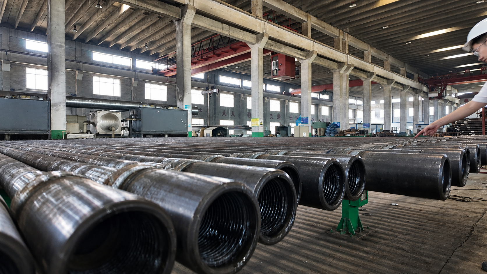
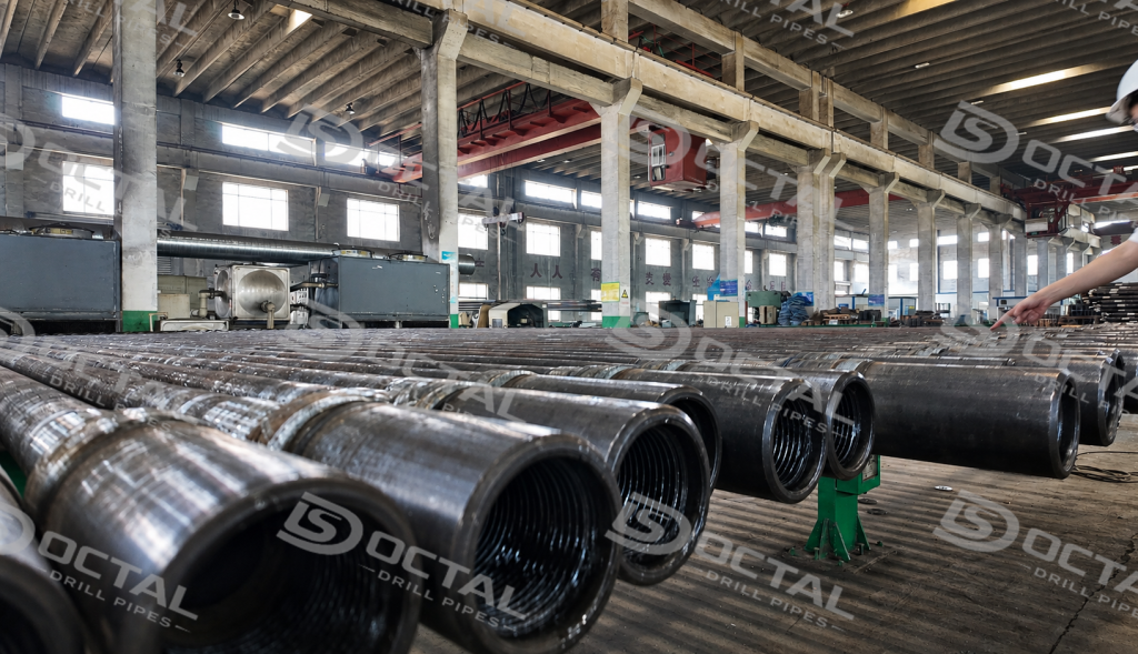
Drill pipe manufacturing combines a heat-treated seamless pipe body with separately produced tool joints to form a complete load-bearing drill string component. The pipe ends are upset to increase the local cross-section, while the tool joints are heat treated and machined with pin and box rotary shouldered connections. The two parts are then joined by friction welding, followed by weld-zone heat treatment, dimensional verification, nondestructive examination, and final traceability control before release.
Oilfield steel drill pipe for petroleum and natural-gas drilling uses an upset seamless pipe body with separately manufactured weld-on tool joints. This construction differs from HDD drill rods and DTH drill pipes, which may use different body designs and joining methods. For API/ISO drill pipe, the main manufacturing controls are the pipe body, upset ends, tool joints, friction-welded interfaces, rotary shouldered connections, and final traceability.
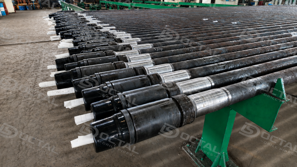
For buyers and drilling engineers, the important question is therefore not only which production steps are used. The more useful question is what each step controls: the pipe-body strength, upset transition, tool-joint geometry, friction-weld zone, connection accuracy, or final traceability.
Drill Pipe Manufacturing Process at a Glance
A practical way to understand drill pipe manufacturing is to separate it into two production routes.
The first creates the pipe body. The second creates the drill pipe tool joint. The two components meet during final assembly.
| Production Route | Main Manufacturing Operations | Main Control Objective |
|---|---|---|
| Pipe body | Seamless tube verification → upsetting → heat treatment → straightening → dimensional and NDT inspection → weld-end preparation. | Mechanical properties, body geometry, upset transition and material integrity. |
| Tool joint | Material preparation → heat treatment → OD/ID machining → shoulder machining → pin/box connection machining → gauging. | Connection strength, dimensions and mating geometry. |
| Final assembly | Friction welding → flash removal → weld-zone heat treatment → NDT → connection verification → marking and release. | Body-to-tool-joint integrity, alignment and complete traceability. |
This two-route structure reflects the actual construction of API/ISO steel drill pipe. ISO 11961 specifies steel drill pipe with upset pipe-body ends and weld-on tool joints, while API also treats drill pipe bodies, tool joints, and completed drill pipe as distinct manufacturing elements within its certification framework.
The exact equipment arrangement can differ from one mill to another. For that reason, a professional description of the drill pipe production process should focus on controlled manufacturing results rather than claiming that every plant uses one identical machine sequence.
Pipe Body Manufacturing: From Seamless Tube to an Upset Drill Pipe Body
The pipe body forms the long load-carrying section of the drill string. During drilling it is exposed to tension, torque, internal fluid pressure, bending, and repeated cyclic loading. Its manufacturing route therefore has to control both material properties and dimensional stability.
Seamless Tube Verification Comes Before Forming
Production starts with a seamless steel tube selected for the required grade and dimensional configuration.
Before the tube enters upsetting and heat treatment, the manufacturer needs to retain its material identity and confirm that the starting condition corresponds to the production order. Important checks include tube identification, heat or lot reference, outside diameter, wall thickness, surface condition, and applicable material documentation.
Material traceability is maintained from the incoming seamless tube through upsetting, heat treatment, straightening, welding, and final inspection. Heat/lot identification and inspection records remain linked to the finished drill pipe so that mechanical-test and NDT results can be verified against the physical joint during final release.
Drill Pipe Upsetting Process
The drill pipe upsetting process modifies the pipe ends before tool joints are attached.
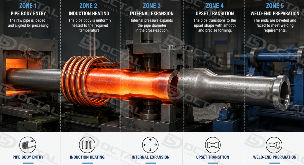
A green tube normally has a relatively uniform wall section. During upsetting, the end is heated and plastically formed so that the local section becomes shorter and thicker. This increases the cross-sectional area available at the pipe end and creates the geometry needed for later connection to the heavier tool joint.
After upsetting, the enlarged pipe end is prepared to provide the required geometry for weld-end machining and subsequent friction welding to the tool joint.
The engineering point is not simply that “a thicker end is stronger.” What matters is the transition between the normal pipe body and the enlarged end.A well-controlled upset should avoid an unnecessarily abrupt change of section. The transition also needs to maintain suitable concentricity because this area eventually sits between the flexible pipe body and the much heavier tool joint. Under rotating bending and tensile loading, poor transition geometry can increase local stress concentration.
Depending on the specified drill pipe design, upset configurations can include internal upset, external upset, or internal-external upset. The actual upset type should be taken from the ordered drill pipe configuration rather than inferred from pipe size alone.
Drill Pipe Heat Treatment
After upsetting, the pipe body is heat treated to achieve the mechanical properties required for the specified drill pipe grade. For quenched-and-tempered drill pipe, heating, quenching, and tempering are controlled as a continuous production sequence. The finished condition is verified by the required mechanical-property and hardness tests rather than by furnace parameters alone.
After heat treatment, the pipe body is checked for mechanical properties, hardness, dimensions, and straightness before weld-end preparation. Grade requirements for E75, X95, G105, or S135 are verified against the applicable API 5DP / ISO 11961 requirements and the ordered product specification.
The friction-weld zone is heat treated separately later in production, after the tool joint has been welded to the upset pipe body and the weld flash has been removed. This local treatment controls the metallurgical condition of the welded area before hardness verification and NDT. Pipe-body heat treatment and weld-zone heat treatment are therefore recorded as separate manufacturing operations.
Straightening and Dimensional Control
Heat treatment is followed by geometry control because mechanical properties alone do not produce an acceptable drill pipe.
The pipe body has to maintain the straightness and dimensional condition required for later weld preparation and final assembly. OD, wall condition, straightness, upset geometry, and alignment all affect how accurately the pipe body can be joined to the tool joint.
This matters because the finished drill pipe forms one rotating load path. A strong pipe body with excessive runout or poor end concentricity can still create problems at the friction-weld transition.
Pipe Body and Upset-End Inspection
Nondestructive examination must match the geometry being inspected.
The long constant-section body can be examined using suitable automated methods such as ultrasonic or electromagnetic inspection according to the applicable specification and production plan. The upset end is more complicated because its wall thickness and transition geometry differ from the normal pipe body.
For this reason, it is better to describe inspection by controlled area:
- normal pipe body;
- upset transition;
- end preparation area;
- later, the friction-weld zone.
A statement such as “the pipe receives UT” does not by itself explain whether all critical regions have actually been examined.
Tool Joint Manufacturing and Connection Preparation
The tool joint should not be treated as a ready-made fitting that simply appears at the welding station.
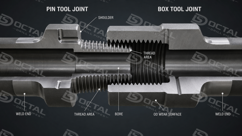
A drill pipe tool joint is a separately manufactured, heat-treated, and machined component. It provides the enlarged connection section at each end of the pipe and carries the rotary shouldered connection used to join one drill pipe to the next.
- Tool-Joint Material and Heat Treatment
Tool-joint manufacturing begins with its own controlled material route.The tool joint experiences a different stress and wear condition from the main pipe body. Its larger section contains the threaded pin or box connection, shoulder, bore, and wear surfaces. It therefore has its own material, heat-treatment, hardness, machining, and inspection history before welding.
Finished drill pipe acceptance includes separate verification of the tool joint and rotary shouldered connection. Tool-joint mechanical properties, hardness, machined dimensions, shoulder condition, and pin/box gauging are checked independently from the pipe-body grade requirements.
- Tool-Joint Machining
After heat treatment, tool joint machining establishes the dimensions required for both connection performance and final welding.Important machined areas include the outside profile, internal bore, connection shoulder, pin or box region, and weld end.
The shoulder deserves particular attention. In a rotary shouldered connection, the threaded connection and shoulder work together during make-up and torque transfer. A thread can therefore be dimensionally close to specification while poor shoulder condition still prevents satisfactory connection performance.The weld end also needs a controlled geometry so it can be aligned with the upset pipe body before friction welding.
- Pin and Box Connection Machining
The two ends of the finished pipe provide the pin and box connection needed to build the drill string.Thread machining must control more than the visible thread form. Connection behavior also depends on taper, pitch-related geometry, shoulder condition, alignment, mating compatibility, and the actual connection design.
API Spec 7-2 specifically covers threading and gauging of rotary shouldered connections. API published Addendum 3 to the second edition in September 2025, so buyers specifying API rotary shouldered connections should identify the applicable edition and project requirements rather than relying on the generic phrase “API thread.”
That distinction also helps keep standards correctly separated:
API 5DP addresses drill pipe as a product.
API 7-2 addresses rotary shouldered connection threading and gauging.
Final Assembly: Drill Pipe Friction Welding
The body and tool-joint routes meet during drill pipe friction welding.
This is one of the most important stages in the entire manufacturing process because the weld becomes a permanent part of the structural load path between the relatively thin pipe body and the heavier tool joint.
Preparing the Weld Ends
Before welding, the upset pipe end and tool-joint weld end need compatible mating surfaces.
Turning and facing operations can be used to establish the required end diameter, face condition, and alignment before the two components enter the welding machine. Tejas describes this preparation as a “turn and face” operation used to create consistent weld surfaces before inertia welding.
This step prevents an important misconception: friction welding cannot be expected to correct major dimensional or alignment errors created earlier in production.
The required load path has to be established before welding:
pipe body → upset transition → prepared weld interface → tool joint.
How Friction Welding Forms the Joint
During rotary or inertia friction welding, one component rotates relative to the other while axial force brings the prepared surfaces into contact.
Friction generates heat at the interface. The material near the surfaces becomes plasticized, and axial loading displaces heated material from the interface. The process then completes the joint through a forging action rather than conventional melting of a large weld pool.
This is a solid-state joining process. During friction welding, concentricity and key process parameters such as rotational speed, axial force, and cycle time are controlled and recorded for each joint. The actual settings depend on the pipe-body and tool-joint configuration and are established by the qualified welding procedure rather than fixed as universal API values.
After welding, the joint proceeds to flash removal, weld-zone heat treatment, and inspection before final acceptance.
Weld Alignment and Load Transfer
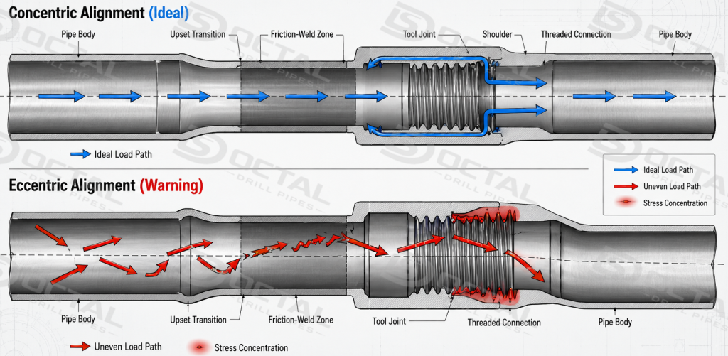
The friction-welded connection must maintain proper alignment between the pipe body and tool joint so that axial load, torque, and bending can pass smoothly through the upset and weld transition. Concentricity is therefore controlled as part of the welding process, not simply checked as an external dimensional feature.
Excessive eccentricity can shift the load path away from the drill pipe centerline and create higher localized cyclic stress during rotation and bending. For this reason, alignment of the pipe body, weld interface, and tool joint is verified together with weld integrity before the assembly proceeds to subsequent heat treatment and inspection.
Weld Flash Removal
Friction welding displaces plasticized material away from the interface and forms weld flash.
The presence of flash immediately after welding is part of the joining mechanism; it should not automatically be described as a weld defect. The flash is subsequently removed from the appropriate internal and external areas so that the finished bore and outside transition can be machined and inspected.
Internal finishing is particularly relevant because drilling fluid must pass through the bore of the completed drill pipe without an unintended local obstruction.
Weld-Zone Heat Treatment
After friction welding and flash removal, the weld zone is heat treated separately from the pipe body and tool joint. This controls the local metallurgical condition created at the welded interface.
The weld zone is then checked by hardness testing and nondestructive examination before final dimensional and connection inspection. Records for the pipe body, weld zone, and tool joint remain traceable through final release according to API 5DP / ISO 11961 and the project specification.
Each has a different manufacturing history and therefore requires appropriate production and inspection evidence.
Inspection and Final Release
Drill pipe inspection continues throughout manufacturing, but final release confirms that the pipe body, upset ends, tool joints, friction-welded zones, and threaded connections together meet the specified product and purchase requirements. Final verification typically reviews dimensional condition, alignment, mechanical-test results, applicable nondestructive examination, weld-zone condition, and pin/box connection quality before the finished joint is accepted for shipment.
Traceability is an important part of this stage. The identity of each finished drill pipe should remain connected to the relevant starting material, heat-treatment lot, tool-joint manufacturing records, friction-welding records, post-weld heat treatment, and inspection results. This allows the completed joint to be evaluated according to its actual manufacturing history rather than only by its final appearance or grade marking.
Before release, the finished drill pipe is also checked for correct product identification, connection protection, and the documentation required by the applicable specification and purchase order. The final acceptance therefore confirms both the physical condition of the drill pipe and the consistency of the records supporting its manufacture and inspection.
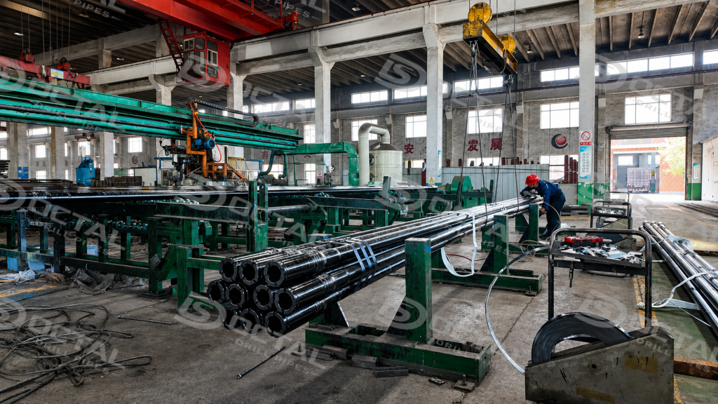
Optional Finishing Processes Before Shipment
The core API 5DP drill pipe manufacturing sequence should be separated from processes that depend on the purchase order.
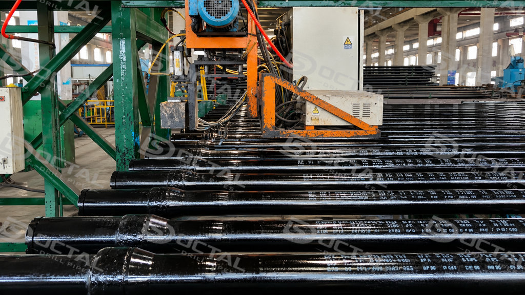
Hardbanding may be applied to selected tool-joint OD areas when wear protection is required. Connection surface treatment may be specified to support make-up performance or handling. Internal coating can be added where the service and purchase specification require it. Finished pin and box ends are also protected during handling and transportation.
These operations are useful, but they should not be presented as mandatory manufacturing steps for every drill pipe.That distinction keeps the article technically accurate and helps buyers separate:
Hardbanding, internal coating, and connection surface treatments are order-specific operations rather than universal steps in drill pipe manufacturing. Their application depends on the connection design, drilling conditions, wear requirements, and project specification.
Manufacturing Control Across the Drill Pipe Load Path
A finished drill pipe transfers axial load, torque, bending load, and drilling vibration through the pipe body, upset transition, friction-weld zone, tool joint, and rotary shouldered connection. Because these sections are formed and processed separately, their geometry and alignment must remain consistent through final assembly.
At the upset transition, manufacturing control focuses on wall build-up, transition profile, OD/ID concentricity, and straightness after forming and heat treatment. Before friction welding, the upset pipe end and tool-joint weld end are turned and faced so that the mating surfaces, bore, and outside diameter are correctly aligned. After welding, internal and external flash is removed, the weld zone receives the specified post-weld heat treatment, and the joint is checked for weld integrity, hardness condition, alignment, and dimensional conformity.
The tool joint and connection are controlled separately through OD/ID machining, shoulder machining, pin or box thread cutting, and connection gauging. Thread profile, taper, lead, shoulder condition, bore alignment, and connection dimensions are verified according to the applicable API 7-2 / ISO 10424-2 connection requirements, while the completed drill pipe is released according to API 5DP / ISO 11961 and the ordered project specification.
FAQ
Why are drill pipe ends upset before the tool joints are welded?
Upsetting increases the cross-sectional area at the pipe end and creates the transition required for joining the relatively thin pipe body to the heavier tool joint. The geometry of this transition also affects alignment and local stress distribution during cyclic drilling loads.
Why does a friction-welded drill pipe require post-weld heat treatment?
The pipe body and tool joint may already have their required mechanical properties before assembly, but friction welding creates a new local metallurgical region between them. Post-weld heat treatment controls this region before hardness testing and nondestructive examination.
Are the pipe body and drill pipe tool joint manufactured separately?
Yes. They normally follow separate material, heat-treatment, machining, and inspection routes before final friction welding. This is why pipe-body records and tool-joint records should remain identifiable through the final assembly process.
What should buyers check in a drill pipe manufacturing document package?
The document package should allow the finished drill pipe to be linked to its material identity, heat-treatment and mechanical-test records, applicable pipe-body and weld-zone NDT, tool-joint and thread inspection, connection verification, and final product marking. The exact scope should be defined in the purchase order and applicable API/project specification.